Content last revised on September 23, 2026
Preventing Spurious Faults: IFSM Safety Derating across Repetitive Operating Conditions for DD1200S45KL3_B5
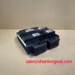
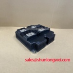
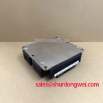
Begin incoming inspection by confirming the marking DD1200S45KL3_B5, checking the terminal layout against the original equipment documentation, and recording cold-state diode measurements before applying any power. The Infineon unit is specified as a high-voltage diode module with a 4500 V repetitive peak reverse voltage, a 11000 A surge forward current at 10 ms and 125°C, a 14.3 K/kW junction-to-case thermal resistance, and a 6000 V RMS insulation test voltage at 50 Hz for 1 minute.
| Parameter | Official Specification |
|---|---|
| Manufacturer | Infineon |
| Product category | Diode Module |
| Repetitive Peak Reverse Voltage, VRRM | 4500 V |
| Surge Forward Current, IFSM | 11000 A at 10 ms and 125°C |
| Thermal Resistance, Junction to Case, RthJC | 14.3 K/kW |
| Insulation Test Voltage, VISOL | 6000 V RMS, 50 Hz, 1 minute |
For a medium-frequency induction melting or metal hardening power supply, the 11000 A surge forward current rating is an official device specification for the stated test condition. It should not be treated as a continuous operating-current rating or as a substitute for a complete short-circuit coordination study. During incoming inspection, engineers should compare the rectifier position, AC source impedance, upstream fuse characteristics, and the equipment’s measured fault-current envelope with the original design documentation.
The 10 ms condition is important when reviewing a line-frequency fault or half-cycle surge event. The system designer should verify how quickly the protective fuse clears and whether its available I2t coordination is compatible with the module’s approved application data. The necessary fuse coordination table is not included in the supplied product parameters, so a definitive fuse rating or I2t value should not be assigned to this device page.
Before reverse voltage is reapplied after a surge event, inspect the module for package damage, terminal discoloration, loose hardware, and evidence of abnormal heating at the mounting interface. A diode test on an isolated, fully discharged module can help identify an open or shorted junction, but the result must be interpreted using the actual terminal topology and a known-good reference. A single multimeter reading is not sufficient to validate high-voltage reverse blocking performance.
💡 Bench Tip: Use ESD precautions, isolate all external conductors, and compare cold-state forward readings with a documented known-good unit before making a replacement decision.
Benchtop Waveform Tuning: Industrial Surge Protection around DD1200S45KL3_B5
IEEE 61000-4-5 testing belongs to the equipment-level surge-immunity assessment, not to the diode module’s standalone rating. When this Infineon module is evaluated in an AC input rectifier for an induction heating supply, the protection network should be reviewed as a complete path that includes the incoming switchgear, fuses, surge arresters, bus capacitors, wiring inductance, and diode junctions.
MOV selection is system-determined. The integrator should verify the nominal AC voltage, maximum supply voltage, temporary overvoltage exposure, energy capability, clamping behavior, and coordination with upstream protection before selecting a device. An MOV that clamps too aggressively may introduce unwanted current or thermal stress, while one with excessive clamping voltage may leave the rectifier exposed to a transient beyond the intended operating boundary.
RC snubber placement should also be assessed from the measured commutation waveform rather than copied from a generic circuit. Use an oscilloscope and suitable differential probing to observe voltage overshoot, ringing, and recovery behavior at the rectifier terminals. The objective is to reduce parasitic oscillation and limit transient stress while keeping the snubber’s switching loss and resistor heating within the system’s thermal budget.
Infineon’s power semiconductor guidance for OptiMOS™ and CoolMOS™ power MOSFETs provides useful general background on switching-device protection, although those MOSFET product families should not be treated as electrical substitutes for this diode module. For an industrial power assembly, oscilloscope validation should be completed with the final bus structure, cable routing, protective devices, and load connected.
Assembly Integrity and Layout Architecture for High-Voltage Rectification
DD1200S45KL3_B5 is identified in the supplied data as a diode module. Gate trigger current, gate pulse rise time, holding current, and multi-pulse firing schemes therefore do not apply to this device unless the surrounding converter contains separate controlled semiconductor stages. No gate-current or gate-drive specification should be inferred from the diode module part number.
Mechanical assembly remains important because the official junction-to-case thermal resistance is 14.3 K/kW. The heatsink surface, baseplate contact, thermal interface material, mounting-hole condition, and terminal hardware should be checked against the manufacturer’s mechanical documentation for the exact package. A specific mounting torque or thermal-grease thickness cannot be stated from the supplied electrical parameter set. Designers should use the approved package drawing and assembly instructions, then verify thermal behavior under the actual load profile.
Keep the high-current commutation path short and mechanically secure to reduce unwanted stray inductance. Power terminals should be cleaned and inspected before installation, with conductor size, lug geometry, insulation clearance, and tightening procedure confirmed against the original assembly documentation. The available data does not provide terminal names, internal diode topology, package dimensions, creepage distance, or clearance values, so those details require confirmation from the applicable Infineon document or the existing equipment drawing.
When a repair team is comparing parts for a different rectifier position, the DDB6U180N16RRP_B37 may be reviewed as a separate diode-module option. Compatibility must be established from voltage, current, thermal, mechanical, insulation, and terminal requirements rather than from package appearance alone.
Transient Dynamics and AC-to-DC Transfer Assessment
In a phase-controlled or semi-controlled induction heating supply, the rectifier’s measured DC output depends on the converter topology, firing control, source impedance, commutation overlap, load characteristics, and operating point. The DD1200S45KL3_B5 itself is a diode module, so it does not define a firing-angle range and should not be assigned a controlled-conduction characteristic without a separate thyristor or switching stage.
For a replacement assessment, first identify whether the original circuit is an uncontrolled diode bridge, a mixed bridge, or a fully controlled rectifier. Then compare the terminal arrangement, reverse-voltage requirement, surge-current duty, thermal path, and insulation test requirement with the original design. The official 4500 V VRRM rating supports reverse-voltage evaluation, while the 6000 V RMS insulation test voltage is relevant to the specified insulation test condition; neither figure independently establishes the complete creepage, clearance, altitude, EMC, or system safety approval of the finished furnace.
Power-factor correction, harmonic suppression, and reactive-power behavior must be measured at the equipment input. Designers should review the AC waveform, DC-link ripple, commutation notches, protective-device operation, and thermal response under representative furnace loading. General information on industrial power-conversion platforms can be cross-checked with Infineon’s CIPOS™ Nano IPM Series resources, while recognizing that an IPM is a different product category.
For high-voltage repair work, insulation verification should follow the original equipment’s approved test procedure. The module’s official insulation value is a defined test rating, not a declaration that the complete induction furnace has passed an EMC, safety, or high-altitude qualification. Engineers reviewing extreme operating conditions may also consult The Ultimate Guide to Industrial TFT LCD Technology as a general maintenance reference, while keeping the electrical qualification of the rectifier assembly tied to its own documentation and test results.