
Content last revised on September 27, 2026
Assembly Integrity and Layout Architecture for DZ1070N16K
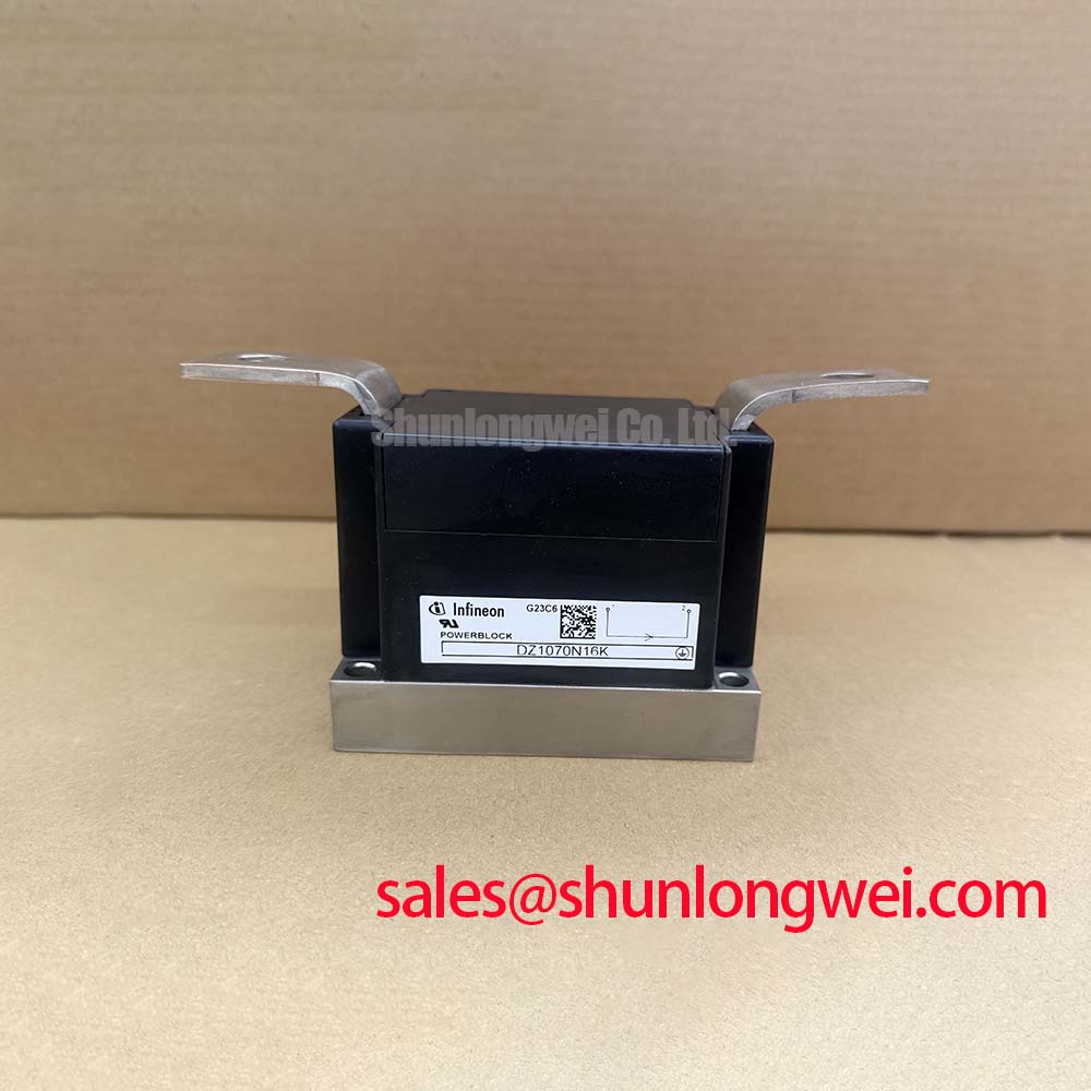
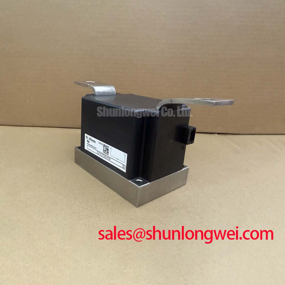
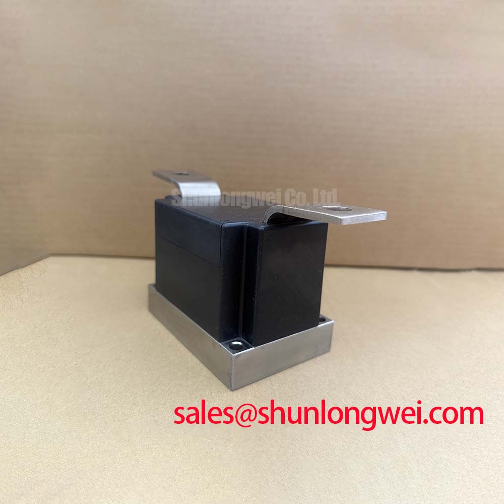
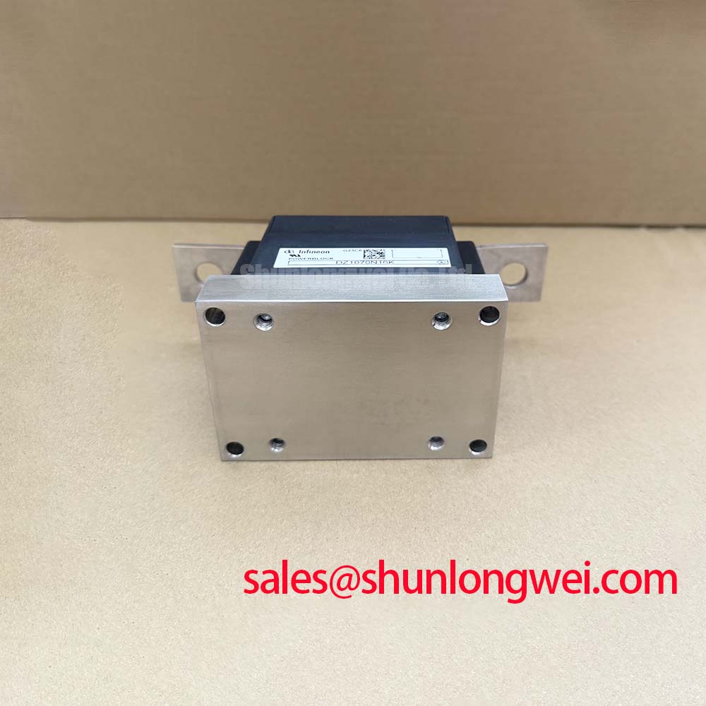
Verify the nameplate rating, inspect the pressure contact surfaces, and check the phase terminal condition before fitting DZ1070N16K into a three-phase motor soft starter. The device is an Infineon diode module with a repetitive peak reverse voltage of 1600 V and an average forward current of 1070 A at TC = 100 °C. Its specified package is a PowerBLOCK pressure contact module, while the supplied product data identifies high I²t capability and optimized junction to case thermal resistance for high density industrial heatsinks.
In a solid state soft starter, the diode path must be evaluated as part of the complete three phase power assembly rather than as an isolated replacement. The applicable topology, terminal arrangement, heat sink construction, phase spacing, semiconductor fuse coordination, and control strategy should all be checked against the original equipment documentation. DZ1070N16K is rated for repetitive reverse voltage of 1600 V, but that rating does not remove the need to assess line transients, commutation conditions, or the actual voltage distribution in the finished starter.
The 1070 A average forward current rating at TC = 100 °C is an official specification. It should not be treated as a direct statement of permissible equipment current under every installation condition. Designers should verify the case temperature, heat sink thermal path, airflow, duty cycle, overload profile, and terminal arrangement used by the soft starter manufacturer. The pressure contact interface also requires clean, even mechanical loading. Uneven clamping can increase contact resistance and create local heating that will not be visible from the electrical rating alone.
For a three-phase power assembly, keep high current paths short and symmetrical where the mechanical layout permits. Minimize parasitic loop inductance to reduce commutation overshoot, then confirm peak voltage with an oscilloscope during controlled switching tests. The actual busbar arrangement, snubber network, fuse type, and motor cable length determine the resulting waveform; they are system design conditions rather than factory specifications of DZ1070N16K.
Fuse coordination must be based on the manufacturer’s semiconductor fuse table and the verified fault withstand data for the complete assembly. The supplied product information confirms a high I²t rating for robust fault tolerance, but it does not provide a numerical I²t value or a specific fuse recommendation. Procurement and maintenance teams should therefore obtain the applicable fuse coordination information before approving a replacement or changing the upstream protection device.
When comparing a related high power device for a particular mechanical or electrical envelope, engineers may review DDB6U180N16RRP_B37 as a separate product record. It should be assessed independently for voltage class, current rating, package geometry, thermal interface, and approved application conditions rather than assumed to be a direct substitute.
DZ1070N16K Operational Boundaries and Commutation Evaluation
A diode module in a soft starter experiences repeated line commutation, and the switching waveform is affected by source impedance, motor characteristics, cable inductance, firing timing, and the parallel protection network. The supplied factory data does not specify reverse recovery charge, reverse recovery time, reverse recovery peak current, or a soft recovery classification for DZ1070N16K. Those values must not be inferred from the 1600 V voltage rating or the 1070 A current rating.
For engineering evaluation, capture the voltage across the module and the current through the relevant phase path during startup, bypass transfer, controlled stopping, and abnormal interruption tests. Compare the measured reverse recovery behavior with the original design record. Excessive recovery current or ringing may indicate an interaction between the device and the surrounding commutation loop, but it should not be assigned to the diode alone without checking gate timing, snubber condition, wiring symmetry, and measurement probe technique.
Where the soft starter uses a separate rectification or auxiliary power stage, the system engineer may also examine the role of TT570N16 within the wider topology. This link describes a separate component and does not establish electrical compatibility with DZ1070N16K. The supply voltage, terminal function, and protection sequence must be confirmed from the original equipment documentation.
Thermal measurements should be taken at accessible heat sink locations near the pressure contact interface and at the surrounding busbar connection after the unit reaches a repeatable operating condition. A rising contact temperature can have several possible causes, including surface contamination, uneven pressure, loosened hardware, excessive current imbalance, or degraded thermal material. Use comparative measurements across phases and inspect the mechanical assembly before drawing a component-level conclusion.
The Infineon material on Infineon Intelligent Power Modules provides broader manufacturer information on power semiconductor integration. It should not be used as a substitute for the specific DZ1070N16K data sheet when confirming reverse recovery limits, insulation specifications, or switching behavior.
DZ1070N16K Thermal and Electrical Optimization for AC Line Transients
The 1600 V repetitive peak reverse voltage rating establishes an important device boundary, but it is not a complete surge protection specification for a motor soft starter. AC line disturbances, transformer impedance, switching events, lightning exposure, and the installation earthing arrangement can create transient conditions that require system-level protection. Surge testing and protection selection should be performed against the applicable equipment standard and the actual installation category.
MOVs, RC snubbers, and semiconductor fuses should be selected from verified clamping, energy, pulse repetition, insulation, and coordination data. The supplied product record does not state an MOV voltage, snubber capacitance, snubber resistance, surge current limit, or IEC 61000-4-5 test result for DZ1070N16K. These values are therefore system design decisions. Designers should verify that the protection network limits the measured transient to an acceptable level while avoiding excessive leakage, repetitive heating, or unwanted commutation behavior.
Keep the surge protection loop physically compact and separate high energy discharge paths from sensitive control wiring. Confirm the protective earth path, creepage and clearance arrangement, enclosure condition, and cable routing during a maintenance inspection. A module can retain correct cold resistance measurements while the surrounding protection network has aged, cracked, loosened, or changed its leakage behavior.
The module’s optimized junction to case thermal resistance is identified in the supplied product information as a feature for high density industrial heatsinks. No numerical RthJC value is provided, so thermal design must use the applicable manufacturer data together with the actual heat sink, interface material, mounting pressure, ambient temperature, and duty profile. Do not calculate a final thermal margin from the product category alone.
Maintenance Note: Clean the heat sink air path and check phase-to-phase contact temperature during scheduled service, especially after prolonged operation in dusty or humid enclosures.
DZ1070N16K Fault Coordination and Sub-Cycle Short Circuit Assessment
A dead short on the line side or load side can subject a power module to a current pulse before the protective device clears the fault. DZ1070N16K is described as having a high I²t rating for robust fault tolerance, but the supplied data does not include a numerical I²t withstand value, clearing time, semiconductor fuse class, or type 2 coordination result. A claim of zero damage during a short circuit cannot be made without the complete manufacturer coordination data and a validated equipment test.
During a protection review, record the available fault current, source impedance, fuse pre-arcing and clearing characteristics, busbar inductance, and the module’s specified short-duration withstand information. The fuse clearing energy must be compared with the verified device withstand limit under the actual temperature and mounting conditions. This is an engineering calculation only when every required manufacturer value is available; it should not be derived from the 1070 A average forward current rating.
Inspection after a fault should include the pressure contact surfaces, phase terminals, heat sink flatness, fuse indicators, snubber components, and insulation barriers. Measure the affected phase against a known-good phase using an approved isolated test method, then compare the result with the original equipment service procedure. An unusual reading may indicate stress in the module or another connected component, so the surrounding circuit should be isolated before a replacement decision is made.
For installations exposed to high altitude, repeated lightning activity, or unusual radiation conditions, the system owner should obtain the applicable derating and reliability information from the equipment and semiconductor manufacturers. The available product data does not provide FIT figures, cosmic-ray limits, single-event burnout limits, operating altitude derating, or field lifetime figures for DZ1070N16K. Engineers researching switching device reliability can consult the Wide Bandgap Revolution guide for broader technology context, while keeping the final qualification tied to the actual diode module documentation.
Before returning a repaired soft starter to service, verify the 1600 V reverse voltage boundary, the 1070 A at TC = 100 °C current specification, the pressure contact assembly, the heat sink interface, the fuse coordination record, and the measured phase balance under controlled commissioning conditions.