Content last revised on October 3, 2026
Field Diagnostics & Commissioning: Drive-Circuit Assessment for 1DI400A-140
With the equipment isolated and the DC link verified discharged, compare cold measurements across the power terminals of the installed 1DI400A-140 against the equipment service documentation before removing the module. Record meter polarity and probe placement; a single resistance reading cannot establish whether the transistor, its external protection circuit, or a parallel current path is responsible for a fault.
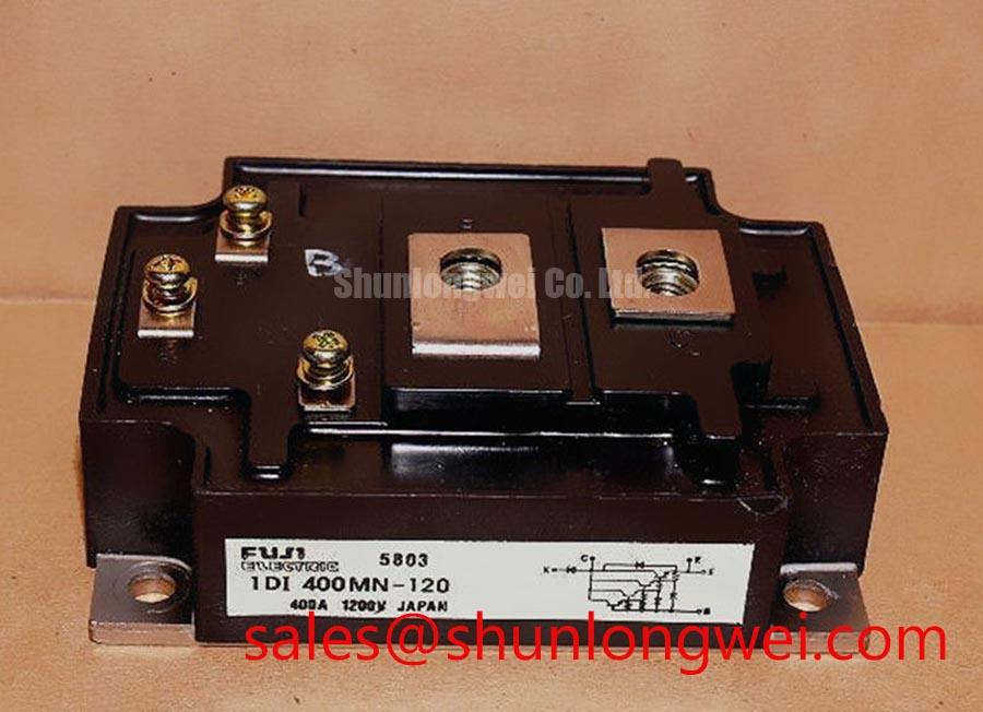
The 1DI400A-140 is identified here as a Fuji Electric power transistor / Darlington module in a power transistor module package, with a stated rated current of 400.0 A (Official Specification). The supplied specification describes its working voltage only as “Standard Industrial Rating”; it does not provide a numerical voltage limit. Procurement and repair teams should therefore obtain the exact device documentation and confirm voltage, terminal assignment, mounting details, and operating limits before approving a replacement. In particular, a Darlington transistor must not be treated as an IGBT simply because both appear in high-power converter equipment.
An active Miller clamp is an IGBT gate-drive technique, not a feature established for this Darlington module. A proposed repair that retains an IGBT driver should stop at the schematic review: the engineer needs to confirm the installed device’s control terminals and the drive method required by the original equipment. Neither a negative gate-bias value nor an active clamp connection can be specified for the 1DI400A-140 from the supplied product data.
For a field diagnosis, trace the control path from the driver board to the module terminals using the equipment wiring diagram. Check connector condition, terminal identification, and continuity with power removed. If a fault appears only during switching, capture the control signal and collector-emitter waveform with appropriately rated instrumentation, then compare them with a known-good channel under the same operating conditions. Coupled switching noise, a driver fault, and a damaged power device can produce overlapping symptoms; waveform evidence helps distinguish them without assigning a cause from one static meter reading.
Design Consideration: Keep control wiring away from high-current switching paths where practical, and assess insulation spacing against the equipment’s documented voltage and installation requirements. The system engineer must validate switching behavior at the actual DC-link conditions. Fuji Electric’s IGBT module information is useful for recognizing the distinction between IGBT integration practices and this Darlington-module assessment; it is not a specification for the 1DI400A-140.
Transient Dynamics & Electrical Design: Thermal Response of the 1DI400A-140
During a pulsed overload, the heatsink temperature does not immediately reveal the semiconductor junction temperature. Heat moves through the module and its mounting interface over time, so a brief electrical event and a sustained load require different thermal evaluations. A numerical peak-junction-temperature estimate would require this model’s verified transient thermal impedance, applicable temperature limits, and the measured loss waveform. Those values are not present in the supplied specification; a multi-RC result cannot responsibly be calculated from the 400.0 A (Official Specification) current rating alone.
When reviewing a repair, collect the load-current history, switching conditions, cooling arrangement, and temperature measurements from the equipment. Compare the observed duty cycle with the original design record before interpreting a trip as a module fault. A blocked air path or deteriorated thermal interface can change the measured response without changing the device’s electrical rating. For extreme-duty assessments, IGBT Design & Integration provides broader switching and thermal-management context, but its IGBT gate-drive guidance should not be transferred directly to a Darlington transistor.
Driver sourcing and sinking capability, as well as any external damping component, must be assessed against the verified Darlington drive circuit and measured switching waveforms. The IGBT concept of selecting an external gate resistor does not establish a resistor value or drive-current rule for this module. Design Consideration: If ringing appears during testing, examine the measurement setup, wiring path, and driver behavior together; the equipment designer should determine any circuit change after checking device stress under the intended load.
Preventing Spurious Faults: Heatsink Contact and Mounting Guidelines for 1DI400A-140
Before fitting a module, inspect the heatsink contact area for debris, corrosion, raised edges, and remnants of the previous thermal-interface material. Check the module’s mating surface without attempting to reshape it. A visibly uneven interface calls for inspection of the mounting arrangement and the manufacturer’s applicable instructions, not an assumed paste thickness or a generic torque setting.
Apply or replace thermal-interface material according to the material and equipment instructions, aiming for consistent contact without trapped debris or obvious voids. Seat the module evenly and tighten its mounting hardware in the sequence and to the torque specified for the verified assembly. The supplied product information does not establish a fastener size, torque, interface thickness, or allowable baseplate curvature for the 1DI400A-140; presenting any of those as an official limit would make a repair harder to validate.
⚠️ Maintenance Note: Monitor contact temperature trends and check the cooling air path during scheduled service before attributing a rising temperature solely to the module.
For a repeat temperature alarm, record heatsink condition, fan operation where applicable, ambient conditions, load, and the temperature-sensor location. Inspect terminal tightness against the equipment service procedure with power isolated. Moisture or condensation around an industrial enclosure also warrants attention before recommissioning, but its presence does not by itself identify the failed part.
When evaluating another power module, compare the complete documented electrical and mechanical requirements rather than current rating alone. The QM100HY-2H is a separate part to examine during a documented selection review, not a verified drop-in substitute for the 1DI400A-140. Inverter or micro-grid storage equipment provides a possible context for such a review only when the original circuit, operating limits, and mounting arrangement have been confirmed.
Transient Dynamics & Electrical Design: Collector-Emitter Fault Detection for 1DI400A-140
Collector-emitter voltage can help a protection circuit recognize abnormal operation, but an IGBT desaturation scheme cannot be assumed to suit this Darlington module. The supplied specification gives no short-circuit withstand time, desaturation threshold, blanking interval, or approved turn-off profile for the 1DI400A-140. In particular, a fixed detection deadline or a two-stage soft-turn-off requirement would be a system prescription, not an official device specification.
At the bench, first identify where the original equipment senses current and voltage and how it latches a fault. With the system made safe, inspect the sensing connections and compare fault records with the observed control and collector-emitter waveforms. A protection trip may reflect an actual load fault, measurement noise, a sensing-path problem, or switching stress. The engineer should establish which condition occurred before changing a threshold or replacing the module.
Design Consideration: Protection must respond quickly enough for the verified device limits while controlling turn-off overvoltage under the equipment’s bus voltage and wiring inductance. Both requirements depend on documentation and switching tests for the complete assembly. Fuji Electric’s brake-chopper IGBT module information illustrates a different documented device category; it does not establish short-circuit performance or protection settings for this Darlington module. Do not release a repaired converter on the strength of an unverified IGBT protection setting.