Content last revised on April 20, 2026
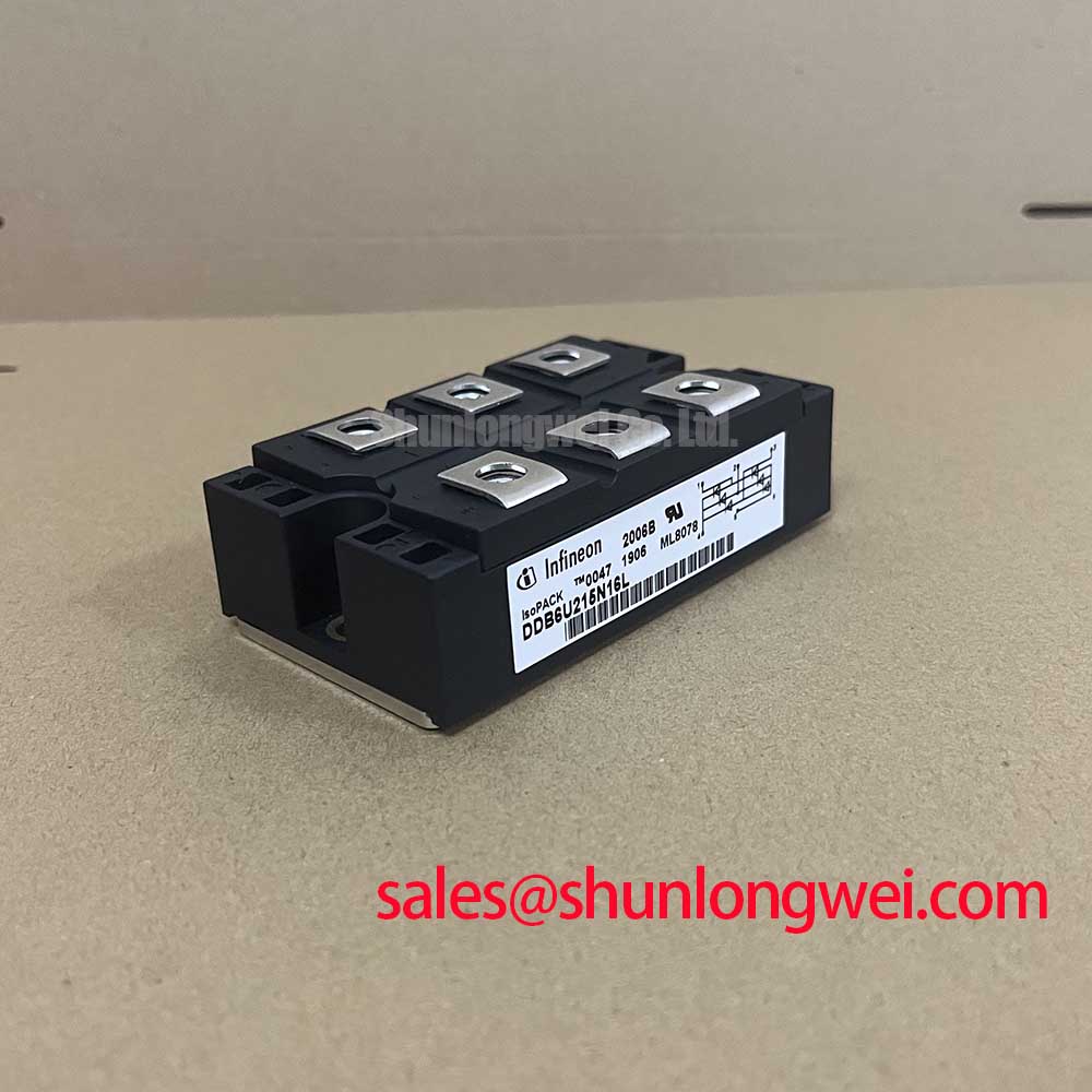
DDB6U85N116L Diode Module: Technical Data for Industrial Drives
Integrated Rectifier and Brake Chopper for Enhanced System Reliability
The Infineon DDB6U85N16L is a highly integrated Diode Module designed to streamline power conversion stages in demanding industrial applications. This component consolidates a three-phase uncontrolled rectifier bridge and a brake chopper (IGBT with a freewheeling diode) into a single, thermally efficient package. Its core value lies in its construction, which leverages an isolated baseplate to ensure robust thermal performance and long-term operational reliability. By integrating these two critical functions, the module simplifies heatsink design, reduces assembly complexity, and enhances the overall dependability of drive systems. What is the benefit of its integrated design? It provides a co-located thermal solution for both rectification and dynamic braking, reducing system footprint.
Integrated Power Control for Demanding Industrial Drives
The dual-function architecture of the DDB6U85N16L makes it a component of choice for systems requiring both AC-DC rectification and the management of regenerative energy. Its robust design is particularly suited for applications characterized by frequent start-stop or dynamic load cycles.
- Variable Frequency Drives (VFDs): As the front-end rectifier and braking unit, it provides the DC bus voltage for the inverter stage while safely dissipating excess energy during motor deceleration, protecting the DC link capacitors from overvoltage conditions.
- Servo Drives: In high-precision robotics and CNC machinery, the module's integrated brake chopper is essential for managing the rapid acceleration and deceleration cycles, ensuring positional accuracy and system stability.
- Elevators and Cranes: These material handling systems generate significant regenerative energy when lowering loads. The DDB6U85N16L offers a compact and reliable solution to manage this energy, improving safety and operational efficiency.
- General Purpose Power Supplies: For industrial power units that may experience back-feeding from connected loads, this module provides a built-in protection and energy management mechanism.
For applications requiring a similar integrated topology but with different current or voltage ratings, the DDB6U145N16L can be considered for evaluation.
Anatomy of Reliability: Isolated Baseplate and Co-packaged Chopper
The long-term performance of a power module is fundamentally tied to its thermal and mechanical design. The DDB6U85N16L is built upon principles that directly address these engineering concerns. The core of its design is the Alumina (Al2O3) DCB (Direct Copper Bonded) substrate, which acts as an electrical insulator while facilitating an efficient pathway for heat to travel from the semiconductor junctions to the heatsink. This isolation simplifies the overall system's electrical design by providing a high dielectric withstand voltage, eliminating the need for separate insulating pads which can degrade over time.
The thermal resistance from junction to case (RthJC) for the rectifier diodes is specified at 0.3 K/W per diode, while the IGBT and its freewheeling diode in the chopper section are rated at 0.25 K/W and 0.4 K/W, respectively. These values are critical inputs for thermal simulations, allowing engineers to accurately predict junction temperatures under various load profiles. Think of thermal resistance as the constriction in a pipe; a lower value signifies a wider pipe, allowing heat to flow away from the sensitive silicon more freely. This efficient heat dissipation is a cornerstone of the module's reliability, as it mitigates thermal stress and slows down aging mechanisms. What defines its long-term stability? Its industrial-grade housing ensures consistent mounting pressure for stable thermal performance.
Streamlining Drive Design: The Value of Integrated Topologies
In the competitive landscape of industrial automation, design efficiency and speed to market are critical. The DDB6U85N16L Diode Module directly supports these objectives by offering a higher level of integration. Consolidating the input rectifier and brake chopper reduces the bill of materials (BOM), minimizes the required PCB footprint, and simplifies the assembly process. This approach is more than just a convenience; it reduces the number of potential failure points—such as interconnects and separate mounting interfaces—thereby inherently increasing the system's mean time between failures (MTBF). For high-power industrial drives, where reliability directly impacts production uptime, this integrated module is the optimal choice over discrete component solutions.
Technical Specifications: Performance and Thermal Integrity
The following table details key parameters of the DDB6U85N16L, providing insight into its electrical characteristics and thermal management capabilities. All data is based on the official manufacturer's datasheet.
| Parameter | Value | Engineering Significance |
|---|---|---|
| Maximum Repetitive Peak Reverse Voltage (VRRM) | 1600 V | Provides a substantial safety margin for operation on 380V, 480V, and even up to 690V AC line voltages, ensuring robustness against line transients. |
| DC Output Current (Id) | 85 A (at TC = 80°C) | Defines the continuous current handling capability of the three-phase rectifier section, forming the basis for sizing the module for a specific motor power. |
| Collector-Emitter Breakdown Voltage (VCES) - Chopper IGBT | 1200 V | Ensures the braking transistor can safely operate on DC bus voltages derived from high AC line inputs without risk of breakdown. |
| Continuous Collector Current (IC) - Chopper IGBT | 60 A (at TC = 80°C) | Specifies the current capacity of the brake chopper, determining the maximum braking torque that can be applied to the motor. |
| Thermal Resistance, Junction to Case (RthJC) - Rectifier Diode | 0.3 K/W | A critical value for thermal design, indicating efficient heat transfer from the diode junctions to the module's baseplate. |
| Isolation Test Voltage (VISOL) | 2500 V (RMS, 50 Hz, 1 min) | Guarantees high electrical isolation between the module's terminals and the mounting baseplate, crucial for system safety and compliance. |
For a comprehensive list of specifications, please refer to the official DDB6U85N16L datasheet.
Deployment Focus: Ensuring Uptime in Material Handling Systems
Consider a conveyor belt system in a logistics warehouse, which frequently starts, stops, and sometimes operates in reverse to manage package flow. Each deceleration event causes the motor to act as a generator, sending a pulse of energy back to the VFD. Without proper management, this energy would elevate the DC bus voltage to dangerous levels. The DDB6U85N16L is deployed as the front-end of such a VFD. Its rectifier section reliably converts the incoming three-phase AC power. During braking, the drive's control logic activates the module's integrated IGBT, which shunts the excess DC bus energy into an external braking resistor. The module's low thermal resistance and robust packaging ensure it can handle these repetitive thermal cycles without degradation, contributing directly to the conveyor system's overall uptime and reducing the need for unscheduled maintenance.
Frequently Asked Questions (FAQ) about the DDB6U85N16L
1. What is the primary advantage of using an integrated rectifier-chopper module like the DDB6U85N16L versus discrete components?
The main benefit is enhanced thermal management and reliability. By housing both the rectifier and brake chopper on a single isolated baseplate, it allows for a unified heatsink solution, ensures matched thermal expansion characteristics, and reduces the number of electrical and mechanical connection points, which are common sources of failure in power systems.
2. How do I determine the correct size for the external braking resistor?
The braking resistor's resistance (Ohms) and power rating (Watts) depend on the motor's power, the inertia of the load, and the required deceleration profile. The datasheet for the DDB6U85N16L provides the maximum current and voltage ratings for the chopper IGBT, which are the primary constraints. System designers must calculate the peak braking power and average power dissipation to select a resistor that operates within the module's Safe Operating Area (SOA).
3. Can this module be used for single-phase AC input?
Yes, while it is a three-phase bridge, it can be used for single-phase applications by utilizing two of the three AC input terminals (e.g., L1 and L2) and leaving the third unconnected. However, the maximum output current will be derated compared to its three-phase rating. Always consult the datasheet or relevant application notes for derating curves.
4. What are the key considerations for mounting this module to a heatsink?
Proper mounting is critical for achieving the specified thermal performance. It is essential to use a thermal interface material (TIM) of the correct type and thickness, and to apply the specified mounting torque to the screws evenly. An uneven surface or incorrect torque can create voids, dramatically increasing the thermal resistance and leading to premature failure. For guidance on thermal design, read about unlocking thermal performance.
5. The datasheet specifies an isolation voltage of 2500V. What does this practically mean for my design?
This rating ensures a high degree of electrical safety, isolating the live power circuit from the grounded metal chassis or heatsink. It simplifies compliance with safety standards like UL and IEC by providing a certified isolation barrier. This robust isolation is particularly important in industrial environments to protect personnel and downstream control electronics from high voltage potentials.
Future-Proofing Your Drive Design
As industrial systems evolve towards higher power densities and greater reliability expectations, the selection of foundational power components becomes increasingly strategic. The DDB6U85N16L offers a design pathway that prioritizes thermal stability and integration. For engineers planning the next generation of industrial drives, leveraging such integrated modules can be a key enabler. Future design efforts should focus on optimizing the complete thermal system—from the module's baseplate to the heatsink and airflow—to extract maximum performance and lifespan from the component, ensuring the final system is not only powerful but also exceptionally dependable.