

Content last revised on November 10, 2026
Field Diagnostics & Commissioning: Saturable Reactor and Snubber Sizing to Protect DF150AC160 Topologies
| Parameter | Official Specification |
|---|---|
| Model | DF150AC160 |
| Brand | SanRex (Sansha Electric) |
| Category | Three-Phase Bridge Rectifier |
| Topology | Three-Phase Diode Bridge |
| Voltage Rating | 1600 V |
| Current Rating | 150 A |
| Package | SanRex Power Module |
| Series | Standard |
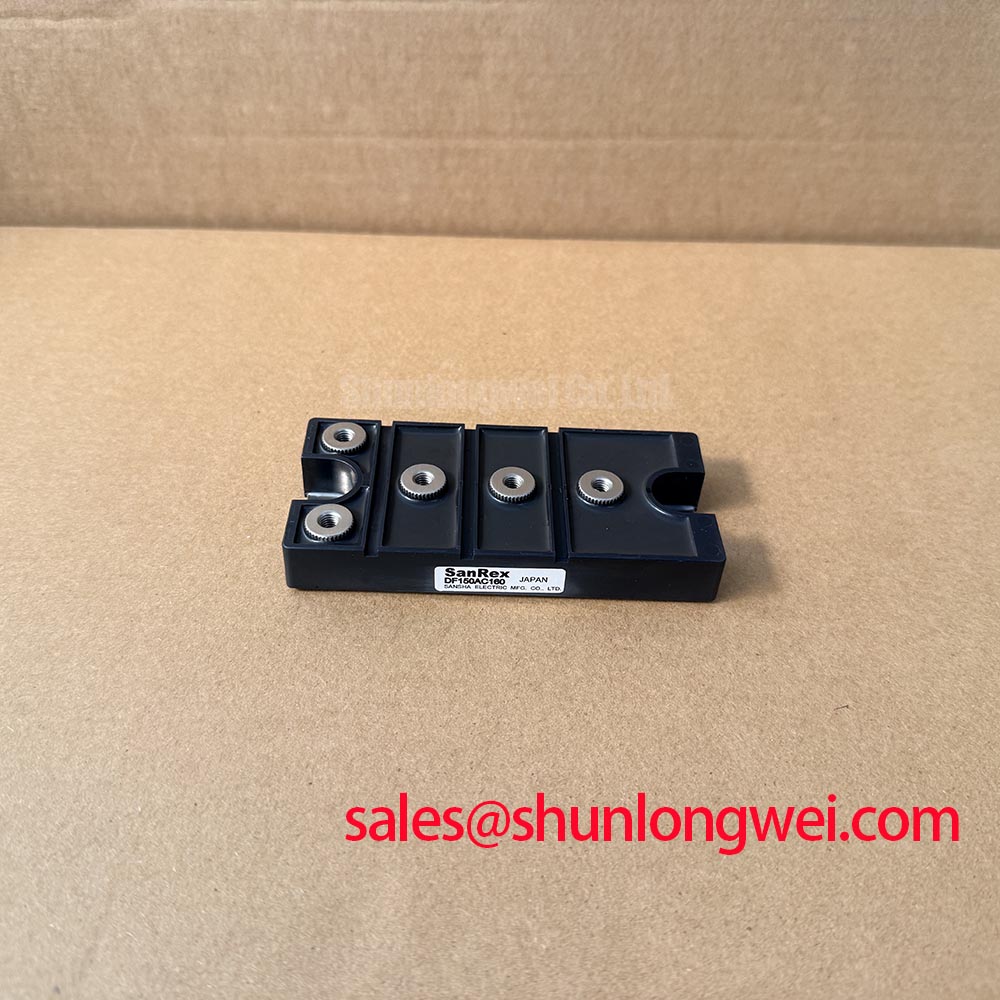
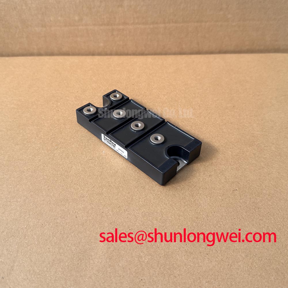
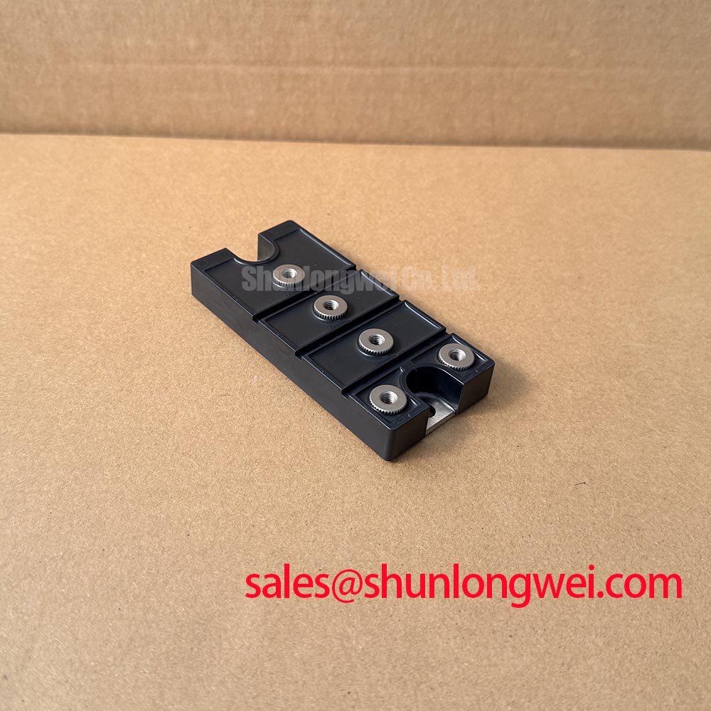
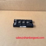
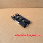
Disconnect the power stage, identify the three AC terminals and the positive and negative DC terminals from the original equipment documentation, then compare each connection with the board marking before taking resistance or diode-mode readings. The DF150AC160 is a 1600 V, 150 A SanRex three-phase diode bridge in a SanRex power module package, so a static test must begin with the correct terminal map rather than an assumed pin sequence.
With the module isolated, use the multimeter diode function to compare the forward conduction paths from each AC input toward the positive DC output and from the negative DC output toward each AC input. Record the polarity, displayed forward voltage, and relative consistency of the three paths at the same bench temperature. The supplied product data does not define a guaranteed forward-voltage acceptance window, so a single meter reading should not be treated as a pass or fail limit. A marked imbalance should be checked against a known-good unit, the surrounding bus connections, and any parallel current path.
For a medium-frequency induction melting or hardening furnace, the snubber and saturable-reactor network is determined by the complete commutation circuit, stray inductance, switching frequency, load profile, and measured transient waveform. This is a Design Consideration, not an official DF150AC160 parameter. Select and tune the network only after observing the AC terminal voltage, DC-link behavior, and current commutation with an appropriately rated differential probe and current probe. The system engineer should verify that peak voltage remains within the rectifier operating boundary during startup, normal load changes, and fault interruption.
Fuse coordination also requires the equipment fuse curve and the manufacturer’s documented I2t data. No fuse I2t value is provided in the supplied DF150AC160 specification, so it should not be inferred from the 150 A rating. Check the actual fuse clearing characteristic, wiring inductance, and prospective fault current before approving the protection network. The Field Engineer’s Handbook can be used as a practical reference for structured bench checks and failure analysis.
DF150AC160 Thermal-Electrical Optimization: High-Frequency Switching Loss Dissipation Practical Tuning
Probe the rectifier AC inputs and DC output during the furnace load cycle, then compare the three phase-current waveforms for unequal conduction, commutation spikes, or abnormal heating at one terminal. The DF150AC160 is specified as a three-phase diode bridge, not as a controlled switching device, so gate-drive dead time and gate resistance are not applicable parameters for this module.
Reverse-recovery peak current and recovery time are important when a diode bridge is placed in a high-frequency power conversion system, but the supplied official parameter set does not specify Irrm, trr, or a soft-recovery classification for this model. These values must therefore be taken from the applicable manufacturer datasheet or characterized under the actual circuit conditions. Do not use a generic recovery waveform as proof of compliance for the DF150AC160.
Thermal investigation should correlate case temperature, heatsink temperature, phase-current balance, switching frequency, airflow, and electrical waveform timing. A rising case temperature can have several interacting causes, including conduction loss, commutation stress, poor thermal contact, uneven current sharing, or an external fault. Compare the physical mounting condition and thermal interface across serviceable units, and confirm that the heatsink arrangement is suitable for the measured dissipation.
When a replacement evaluation is required, the MDS1000A1600V may be reviewed as a separate three-phase rectifier option, but voltage, current, package geometry, terminal arrangement, thermal path, and dynamic characteristics must be matched independently. It should not be treated as an automatic drop-in replacement for the DF150AC160.
DF150AC160 Circuit Protection & Reliability: Calibrating AC Line Surge Immunity and Lightning Transients
Capture the incoming three-phase voltage at the rectifier terminals during contactor closure, transformer energization, and fault clearing, while checking whether the transient is local to the furnace input or produced by the upstream distribution network. The 1600 V voltage rating is an official product specification, but it is not an independent declaration of system-level surge immunity or EMC compliance.
MOV selection, fusing, and any RC snubber stage must be coordinated with the system’s nominal line voltage, grounding method, transformer impedance, available fault current, surge exposure, and required clamping behavior. This is a Design Consideration. IEC 61000-4-5 test levels and coupling networks describe a system test method; they do not establish that an individual DF150AC160 module independently passes the complete equipment test.
Place surge suppression so that its wiring loop is short and its protective current does not share sensitive measurement or control returns. The system designer should verify the MOV energy capability, backup-fuse behavior, leakage current, and post-surge insulation condition under the intended installation category. Check the rectifier terminals for carbon tracking, loosened conductors, discoloration, and mechanical damage after any abnormal surge event.
Field Alert: Keep the DC link fully discharged and verify absence of hazardous voltage before disconnecting the module or removing any power cable.
Benchtop Waveform Tuning: Mitigating Stress via Harmonic Current Injection and Line Filter on DF150AC160
Measure the three input currents and the DC-link voltage together at the operating point where furnace power quality problems appear, then compare the waveform distortion with the line-filter configuration and load condition. A diode bridge naturally draws current in conduction intervals rather than producing a controlled firing-angle waveform, so alpha-based thyristor analysis should not be assigned to the DF150AC160 without a separate controlled front end.
For a medium-frequency induction melting and hardening furnace, evaluate the rectifier as the front-end conversion stage within the complete power topology. Record phase imbalance, current crest behavior, DC-link ripple, transformer heating, and filter resonance during no-load, ramp, and loaded operation. The 150 A rating identifies the official current class of the module; it does not define allowable RMS current for every cooling arrangement, duty cycle, ambient condition, or harmonic spectrum.
Line-filter selection is system-dependent. Designers should check the filter’s impedance against the converter input, avoid creating an uncontrolled resonance, and verify conducted disturbance at the equipment boundary using the applicable installation test method. Harmonic-current mitigation may involve passive filtering, active compensation, transformer selection, or control changes elsewhere in the system. The correct choice depends on measured current spectra and the furnace power architecture.
Where an upstream controlled or complementary rectification stage is present, engineers may also review the MTC160-12 as a separate component reference. Its electrical and mechanical characteristics must be assessed independently from the DF150AC160. For reliability planning, the general discussion of Mean Time Between Failures and Reliability Engineering is a reference concept only; it does not provide field-life data for this module.