


Content last revised on September 29, 2026
MDS1000A1600V Circuit Protection & Reliability: Calibrating Thermal Interface Material Spreading across the Baseplate
| Official Specification | Value |
|---|---|
| Manufacturer | SanRex (Sansha Electric) |
| Model | MDS1000A1600V |
| Product category | Three-Phase Bridge Rectifier Module |
| Rated voltage | 1600.0 V |
| Rated current | 1000.0 A |
| Package | Three-Phase Rectifier Case |
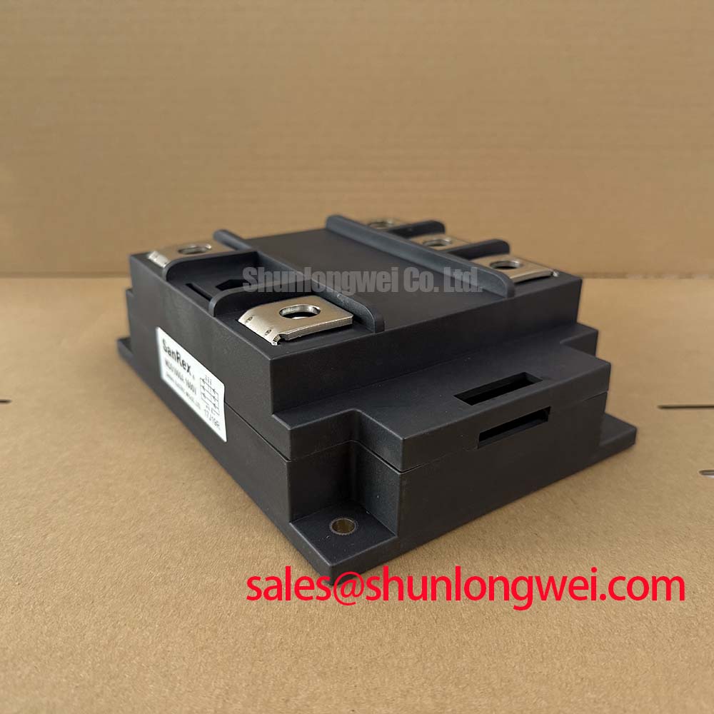
Measure the temperature rise at the module baseplate and heatsink interface under controlled load, then compare readings across the mounting area to identify uneven contact, aged thermal compound, or restricted airflow. The MDS1000A1600V is specified at 1600.0 V and 1000.0 A in a Three-Phase Rectifier Case; these are official product specifications, not guaranteed operating conditions for every installation.
Use a flat, clean heatsink surface and spread the thermal interface material as a continuous, thin layer appropriate to the selected compound. Excess material can increase interface resistance, while incomplete coverage can create localized thermal loading. The final clamping method, contact pressure, and mounting torque must follow the original SanRex mechanical documentation and the equipment manufacturer’s procedure. Do not assign an unverified torque value to this model.
For a high-current green hydrogen electrolyzer DC power rectifier, verify each phase terminal, DC connection, and protective conductor for correct identification and secure mechanical condition. Terminal heating should be checked with thermal imaging or contact temperature measurement during a representative load cycle. A temperature imbalance may involve connection resistance, airflow, current sharing, or heatsink contact, so confirm the result against phase current measurements rather than treating temperature alone as a component diagnosis.
⚠️ Maintenance Note: Schedule heatsink dust removal and thermal-interface inspection as part of preventive maintenance, with contact temperature and airflow checked after reassembly.
Benchtop Waveform Tuning: Mitigating Stress via IEEE 61000-4-5 Industrial Surge Immunity on MDS1000A1600V
Capture the AC input and rectified output waveforms with an appropriately rated differential probe during controlled power-stage operation and surge tests, watching for abnormal overshoot, ringing, or phase imbalance at the rectifier terminals. IEEE 61000-4-5 is an equipment-level surge immunity test framework; the module itself should not be described as independently certified to that standard.
A Design Consideration for the surrounding power stage is coordinated protection using correctly selected fuses, surge arresters, and, where justified by the circuit impedance, RC damping networks. MOV selection must account for the actual line voltage, temporary overvoltage, surge energy, repetition, and enclosure conditions. The MOV’s clamping behavior should be evaluated together with wiring inductance and the rectifier’s voltage rating of 1600.0 V.
Do not select a fuse solely from the module’s 1000.0 A rating. The system designer must compare prospective fault current, fuse clearing behavior, available semiconductor I²t data, and the coordination requirements of the complete protection scheme. The original SanRex technical documentation and the equipment protection study remain the governing sources for any fuse coordination decision.
For manufacturer background and device-family context, engineers can consult SanRex Sansha Electric Power Semiconductor Modules. Bench results should be recorded at the module terminals and at the upstream protection network so that parasitic wiring effects are not mistaken for internal device behavior.
Assembly Integrity & Layout Architecture: Implementing Mitigating DC Ripple Currents in High-Efficiency Systems
Check phase-to-phase current balance and DC ripple directly at the rectifier output before changing the bridge layout or transformer arrangement. A three-phase bridge can be evaluated in six-pulse systems, while twelve-pulse arrangements require a suitable transformer phase shift and controlled current sharing between bridge sections.
When the MDS1000A1600V is considered for a high-current green hydrogen electrolyzer DC power rectifier, the system integrator should verify transformer impedance, conductor symmetry, busbar geometry, and cooling capacity as one electrical and thermal network. Parallel current paths should be physically balanced, with minimized stray inductance and consistent connection resistance. These are Design Considerations determined by the complete power assembly, not additional factory specifications for the module.
Interphase transformer selection and placement should be assessed against the intended twelve-pulse topology, ripple requirements, fault behavior, and available cabinet space. Oscilloscope measurements at the DC bus, combined with phase-current probes, help distinguish transformer imbalance from rectifier-terminal or cabling problems. The three-phase rectifier case should be mechanically supported without twisting or distorting the module body.
For a neutral comparison point during a service review, engineers may examine the VUO121-16NO1 product information, while confirming electrical, mechanical, and thermal compatibility independently before considering any alternate device.
Preventing Spurious Faults: I²t Sub-Cycle Melting Rating Guidelines for MDS1000A1600V
Record the upstream fuse type, prospective short-circuit current, and measured clearing waveform before attributing a dead-short event to the rectifier module. Fuse coordination requires comparison between the fuse’s clearing I²t and the semiconductor’s applicable surge or short-duration withstand data; those values are not provided in the supplied core specification and must not be invented.
The MDS1000A1600V voltage and current ratings establish the product identity at 1600.0 V and 1000.0 A, but they do not by themselves define fault-clearing performance, repetitive surge capability, or guaranteed immunity to installation transients. Confirm the exact SanRex datasheet revision, fuse coordination table, terminal arrangement, and permitted assembly conditions before approving a protection scheme.
During fault investigation, isolate the DC bus, inspect all phase and output connections, and compare semiconductor junction paths with a known-good electrical signature using appropriately rated test equipment. Check for carbonization, loose hardware, thermal-interface displacement, and abnormal busbar contact marks. In a resonant power system, the current path and commutation behavior should also be reviewed through the technical guide on Resonant Topologies in Home Appliances, where applicable to the wider converter architecture.