Content last revised on October 2, 2026
DF1000R17IE4 Thermal Electrical Optimization: Thermal Duty Cycle Management in High Voltage Soft Starter Systems
Before applying power, isolate the assembly and perform a controlled cold inspection of the DF1000R17IE4, checking the enclosure for cracks, distorted mounting surfaces, loose hardware, contamination, and evidence of terminal overheating. Confirm the nameplate identity and compare the replacement unit with the equipment documentation. The available product data identifies this SanRex device as a Three Phase Bridge Rectifier rated at 1700.0 V and 1000.0 A, housed in a SanRex Power Module package. These are Official Specification values for product identification and electrical boundary review.
In a high voltage three phase motor solid state soft starter, the rectifier function must be separated from the phase angle control function. The DF1000R17IE4 should therefore be evaluated according to the actual power topology, switching arrangement, bypass path, and control hardware in the equipment. A bridge rectifier does not, by its product category alone, confirm a phase controlled soft start function or a specific motor inrush reduction performance. The system integrator should verify the schematic, conductor routing, polarity, terminal assignment, cooling arrangement, and control sequence from the original equipment documentation.
Thermal evaluation should follow the complete operating duty rather than the nominal current label alone. Motor acceleration time, restart frequency, ambient temperature, enclosure airflow, conduction losses, and bypass contactor timing all affect the heat transferred into the module mounting surface. A practical Engineering Recommendation is to measure the temperature trend during the longest expected start and during repeated starts, then compare the recorded values with the manufacturer’s applicable thermal limits and installation instructions. Do not infer a permissible continuous current from the 1000.0 A rating without confirming the relevant conditions.
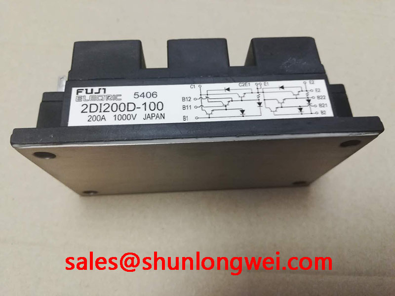
For maintenance teams comparing an existing power assembly with another SanRex product, 2DI30D 050A may be reviewed as a separate device record. It should not be treated as a direct substitute from model numbering alone. Voltage class, current duty, internal circuit arrangement, mechanical dimensions, terminal layout, thermal interface, and control topology require documented comparison before any field replacement decision.
When the module is removed, record cable positions and take photographs before loosening conductors. Inspect each connection for discoloration, looseness, damaged threads, and signs of arcing. Reinstall the module against a clean, flat thermal interface and follow the fastener size, washer arrangement, surface preparation, and tightening torque specified by the equipment or module documentation. A general mounting torque value for a particular bolt size is a Design Consideration, not an Official Specification for this model.
Field Alert: Disconnect and verify the absence of hazardous voltage before removing conductors, and never rely on the control panel indication alone.
Preventing Spurious Faults: Type Two Coordination and Short Circuit Review
A dead short in a high voltage soft starter must be investigated as a system protection event. The DF1000R17IE4 product data supplied for this page confirms the 1700.0 V voltage class and 1000.0 A current class, but it does not provide a verified fuse I²t coordination table, surge current withstand curve, repetitive peak current limit, or short circuit protection guarantee. Those values must be taken from the applicable SanRex datasheet and the fuse manufacturer’s published coordination information before a protection scheme is approved.
The correct field method is to identify the prospective fault current at the installation point, the semiconductor fuse type, the fuse pre-arcing and total clearing I²t, the module’s permitted surge current, and the duration of the fault. The protection engineer can then compare the fuse clearing energy with the rectifier’s documented withstand limits. This is an Engineering Calculation that is valid only when all source values correspond to the installed device, fuse, line impedance, and fault condition. A generic fuse label or a nominal current match is not enough to establish Type Two coordination.
Check whether the equipment uses individual phase protection, a common upstream protective device, or additional branch protection. Confirm the fuse interrupting rating, voltage rating, physical mounting, creepage and clearance, and indication method. The wiring path between fuse and module should be inspected for unnecessary loop area and mechanical damage. Designers should minimize parasitic inductance where fast fault current interruption can generate transient voltage, while the final peak margin must be verified by measurement or validated simulation against the module’s documented blocking capability.
The terminal connection is also part of fault prevention. Loose or contaminated power connections can create localized heating and intermittent voltage stress that may be recorded by the controller as an unexplained rectifier or phase fault. During commissioning, measure phase-to-phase and phase-to-earth insulation according to the equipment service procedure, with the module isolated as required by the manufacturer. Do not apply an insulation test voltage through connected control electronics or sensors unless the equipment documentation explicitly permits it.
Snubber networks, surge arresters, and semiconductor fuses should be assessed as a coordinated protection network. Their presence does not prove that the DF1000R17IE4 is protected under every fault waveform. Verify component ratings, energy capability, thermal mounting, and replacement intervals from their own technical documentation. Any statement about preventing module rupture, guaranteeing zero damage, or achieving a specified clearing result requires a documented test condition and authoritative source.
Field Diagnostics and Commissioning: AC to DC Transfer Checks in DF1000R17IE4 Topologies
Begin commissioning with the equipment isolated, then check the module terminals against the approved schematic rather than assuming a universal pinout. The supplied product information confirms the device category and electrical ratings but does not publish a terminal drawing or internal bridge connection diagram. Terminal names, polarity, auxiliary connections, and permissible test points must therefore be verified from the original SanRex documentation or the equipment manufacturer’s wiring diagram.
For a bridge rectifier used within a soft starter power section, the service engineer should compare the three phase input condition, the rectified output condition, and the downstream DC link or load path. Record phase presence, phase sequence, line imbalance, and the waveform at approved measurement points. A multimeter can identify an open or abnormal static path during a de-energized check, but a cold resistance result is not a substitute for a dynamic withstand test or an oscilloscope measurement under controlled operating conditions.
If the system includes phase angle control elsewhere in the topology, firing angle, conduction interval, power factor, and reactive power are determined by the controlled switching stage and load. They should not be assigned to the DF1000R17IE4 solely because it is installed in the same cabinet. The service engineer should verify the gate or trigger signals at the actual controlled semiconductor stage, then compare the resulting AC waveform and rectified voltage with the approved commissioning limits. Any transfer characteristic must be derived from the circuit topology, supply waveform, motor condition, and measurement location.
During a no-load or reduced-energy test, confirm that the precharge, control supply, interlock, and bypass sequence operate in the intended order. The system integrator should verify the required control voltage from the original equipment documentation rather than assuming a standard value. Monitor for residual voltage after shutdown and follow the equipment discharge procedure before touching the power terminals. Unexpected persistence of voltage may indicate a charging path, a failed discharge circuit, or a measurement setup issue and requires structured isolation.
For troubleshooting, compare the suspect phase with a known-good phase under the same operating condition. A missing waveform, abnormal ripple, or unequal phase behavior may indicate a connection fault, upstream protection issue, rectifier damage, control timing problem, or load-side disturbance. The observation alone does not identify a single cause. Use an isolated differential probe with suitable voltage and transient ratings, document the operating point, and correlate the waveform with protection status and thermal readings.
Before returning the equipment to service, check the mechanical seating, conductor strain relief, enclosure bonding, and airflow path. For panels exposed to dust or water, the enclosure selection should be reviewed against the actual installation environment. The Ingress Protection reference for IP65, IP67, and IP68 describes enclosure protection classifications, while the NEMA enclosure type reference provides another framework for panel protection. These classifications apply to the completed enclosure and installation, not automatically to the rectifier module itself.
DF1000R17IE4 Thermal Electrical Optimization: AC Input Transient Overvoltage Protection
Inspect the AC input protection network before energizing a replacement DF1000R17IE4. Check the upstream fuses, surge arresters, RC networks, contactors, cable routing, earthing conductors, and evidence of previous overvoltage exposure. The module’s 1700.0 V rating identifies its stated voltage class, but it does not define the complete transient environment that the installed power circuit may produce. Peak repetitive voltage, nonrepetitive surge, commutation behavior, line impedance, and protective device coordination must be confirmed from the relevant device and system documentation.
MOV selection is a Design Consideration governed by the normal AC voltage, temporary overvoltage, expected surge waveform, energy duty, protective coordination, and required residual voltage. The integrator should select the operating voltage and energy rating from measured or documented system conditions, then verify that the clamping level remains compatible with the rectifier’s published transient limits. An MOV that is simply chosen from the nominal line voltage can age under repeated temporary overvoltage or fail to provide the intended protection during a high energy event.
RC snubber selection also belongs to the complete circuit design. The network must be evaluated for capacitor voltage rating, pulse current, resistor energy, leakage, resonance, switching frequency, and the location of the switching element. The DF1000R17IE4 product category does not establish a universal snubber value. Designers should minimize voltage overshoot at the module terminals while verifying the actual waveform with appropriately rated instrumentation during switching and interruption tests.
Where the installation references IEC 61000 4 5 testing, the system designer should distinguish between a laboratory surge test applied to the complete equipment and the operating stress experienced by an individual rectifier module. The test generator, coupling network, repetition, polarity, source impedance, and acceptance criteria affect the result. A component cannot be described as independently compliant with the complete equipment EMC or surge standard without a documented system test.
Thermal protection for MOVs and snubber components should be reviewed alongside electrical protection. Provide the required spacing, containment, fuse coordination, and fault indication specified for the selected protection devices. Keep high energy surge paths short and mechanically secure, while ensuring that the protective earth path is intentional and verified. Final acceptance should include insulation checks, functional tests, waveform capture at the approved points, and confirmation that the bypass and shutdown sequence leave no unexpected hazardous energy at the module terminals.
For installation teams assessing cooling interfaces and enclosure heat transfer, the reference article The Advanced Thermal Management Revolution can be used as a general engineering reference. It does not replace the DF1000R17IE4 datasheet, the equipment service manual, or the thermal validation required for the completed soft starter assembly.