


Content last revised on January 30, 2026
Fuji Electric 2DI200-100 IGBT Module: An Engineering Review for High-Reliability Industrial Applications
A Foundation for Robust Power Conversion
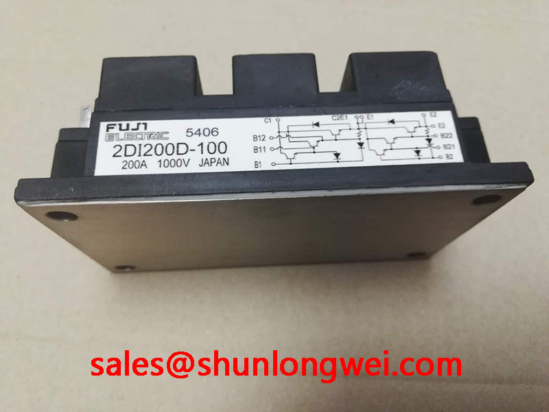
The Fuji Electric 2DI200-100 is a dual IGBT module engineered for enduring performance in demanding industrial power systems. It provides a robust foundation for power conversion through its well-defined thermal characteristics and practical integration. With core specifications of 1000V | 200A | Rth(j-c) 0.14°C/W, this module delivers two primary engineering benefits: simplified thermal management and streamlined half-bridge circuit design. It directly addresses the challenge of achieving long-term operational stability in environments with significant thermal loads. For industrial drives and power supplies where thermal reliability is paramount, the 2DI200-100's proven design offers a dependable power switching solution.
Application Scenarios & Value
System-Level Benefits in Industrial Motor Control and Power Supplies
The 2DI200-100 is best suited for medium-voltage, high-current applications where thermal stability and reliability are critical design drivers. Its 1000V collector-emitter voltage rating provides a safe operating margin for systems running on 480V or 600V AC lines, making it a strong candidate for industrial machinery.
A primary application is in Variable Frequency Drive (VFD) systems for AC motor control. In a manufacturing facility, a VFD might operate continuously, leading to significant heat generation. The engineering challenge is to dissipate this heat effectively to prevent overheating and ensure consistent performance. The 2DI200-100's specified thermal resistance of 0.14°C/W per IGBT is a critical parameter for this scenario. A lower Rth(j-c) value indicates more efficient heat transfer from the silicon chip to the module's baseplate. This allows engineers to design more compact and cost-effective heatsinking solutions, directly impacting the overall system's size and bill of materials. What is the benefit of its efficient thermal transfer? It ensures the IGBT junction temperature remains within its Safe Operating Area (SOA), enhancing the system's long-term reliability and reducing the risk of premature failure.
- Industrial Motor Drives: The half-bridge configuration is ideal for building the inverter legs of a three-phase VFD.
- Welding Power Supplies: Its ability to handle high currents and dissipate heat makes it suitable for the demanding, pulsed-power environment of welding equipment.
- Uninterruptible Power Supplies (UPS): Provides the reliable switching necessary for inverter and converter stages in large-scale UPS systems.
While the 2DI200-100 is a robust choice for 1000V systems, for applications requiring higher voltage blocking capabilities, the related 2MBI300HH-120 offers a Vces of 1200V and a higher current rating of 300A.
Key Parameter Overview
A Functional Breakdown of the 2DI200-100's Specifications
The technical specifications of the 2DI200-100 are foundational to its performance in power circuits. The values below, sourced from the official datasheet, provide the necessary data for system modeling, thermal design, and performance validation.
| Absolute Maximum Ratings (at Tc=25°C unless otherwise specified) | ||
|---|---|---|
| Parameter | Symbol | Value |
| Collector-Emitter Voltage | VCES | 1000V |
| Gate-Emitter Voltage | VGES | ±20V |
| Continuous Collector Current | IC | 200A |
| Pulsed Collector Current | ICP | 400A |
| Collector Power Dissipation (per IGBT) | PC | 890W |
| Operating Junction Temperature | Tj | +150°C |
| Electrical & Thermal Characteristics (at Tj=25°C) | ||
| Collector-Emitter Saturation Voltage (Max) | VCE(sat) | 2.7V (at IC=200A) |
| Gate-Emitter Threshold Voltage | VGE(th) | 5.0 to 9.0V |
| Forward Voltage (FWD, Max) | VF | 2.5V (at IE=200A) |
| Thermal Resistance (Junction to Case, IGBT) | Rth(j-c) | 0.14 °C/W |
| Thermal Resistance (Junction to Case, FWD) | Rth(j-c) | 0.25 °C/W |
Technical Deep Dive
Understanding Thermal Resistance for Long-Term System Reliability
A key to unlocking the reliability of any power module is understanding its thermal performance, and the most critical parameter is the thermal resistance from junction to case, Rth(j-c). For the 2DI200-100, the IGBT's Rth(j-c) is 0.14°C/W. But what does this number mean for a design engineer? What is the practical meaning of thermal resistance? It quantifies how effectively heat generated during operation is moved away from the active semiconductor junction to the module's baseplate.
Think of Rth(j-c) like the width of a water pipe. A wider pipe (lower Rth value) allows more water (heat) to flow through easily, while a narrow pipe (higher Rth value) creates a bottleneck, causing pressure (temperature) to build up. With a low Rth of 0.14°C/W, the 2DI200-100 provides an effective "pipe" for heat to escape. This directly enables a cooler junction temperature for a given power loss, which is crucial for staying within the device's SOA. This characteristic is central to designing a reliable thermal management system and is a key topic explored in guides on unlocking IGBT thermal performance.
Frequently Asked Questions
How does the 2DI200-100's Rth(j-c) of 0.14 °C/W impact heatsink selection for a VFD design?
This value directly influences thermal calculations. A lower Rth(j-c) means the heat generated at the IGBT junction is transferred more efficiently to the module case. This allows engineers to either use a smaller, less expensive heatsink for the same operating current or push more current through the module with a given heatsink, improving power density. It provides greater flexibility and margin in the thermal design phase.
What are the primary advantages of the '2-in-1' half-bridge configuration in the 2DI200-100 for power circuit layout?
The integrated half-bridge (or dual) configuration simplifies the design of inverter legs. Instead of sourcing, mounting, and connecting two separate IGBTs, a single module is used. This reduces component count, minimizes stray inductance in the power loop by providing shorter, optimized internal connections, and streamlines the assembly process, which can lead to higher manufacturing yields and improved system reliability.
Engineering Support and Further Inquiries
For procurement professionals and design engineers requiring specific data for system modeling, sourcing, or integration of the 2DI200-100 IGBT module, our team can facilitate access to further technical documentation. Please contact us for inquiries regarding availability, and technical support to assist in your design and evaluation process.