





Content last revised on October 23, 2026
DF60AA120 Circuit Protection & Reliability: Calibrating Junction-to-Heatsink Heat Dissipation
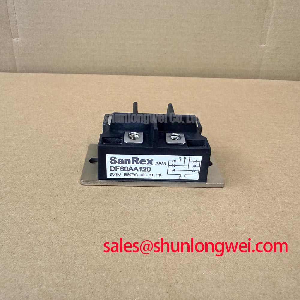
Disconnect the DF60AA120 from parallel circuit paths before checking terminal polarity with a multimeter in diode mode, after isolating the equipment and verifying that stored energy has discharged. Record each conduction path in both probe directions and compare the results with the terminal diagram and a known-good reference measured under the same conditions. A cold diode reading helps identify inconsistent conduction paths; it does not establish rated-current performance or insulation integrity.
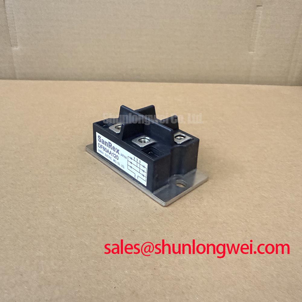
The SanRex DF60AA120 is a three-phase bridge rectifier with specified ratings of 1200 V and 60 A, subject to the datasheet conditions, in a SanRex Power Module package. These electrical ratings identify the component, while the terminal arrangement, thermal conditions, and protection coordination determine its suitability for an existing assembly.
Inspect the heatsink contact surface for contamination, uneven interface coverage, and mounting damage before reinstalling the rectifier. As a Design Consideration, uniform contact pressure helps maintain the intended thermal path without distorting the module housing. Tighten mounting hardware using the applicable manufacturer instructions rather than transferring a torque value from a visually similar package.
Separate junction-to-case thermal resistance from the case-to-heatsink interface when reviewing temperature measurements. The former describes the module’s specified internal thermal path; the latter depends on surface condition, interface material, and assembly quality. A heatsink temperature measurement alone cannot establish junction temperature. For Engineering Recommendation purposes, compare operating current, cooling conditions, and measured temperatures against the manufacturer’s thermal characteristics before returning the assembly to service.
Use SanRex Sansha Electric Power Semiconductor Modules documentation to establish the applicable thermal, mounting, and terminal requirements. Check power-terminal connections separately from mounting screws: their mechanical functions differ, and tightening either joint excessively is not a substitute for clean, properly seated contact surfaces.
Bench Tip: Keep the module isolated from connected electronics when comparing cold diode readings, and never apply an insulation tester through the surrounding control circuitry.
For insulation assessment, distinguish semiconductor blocking voltage from terminal-to-base insulation withstand. The 1200 V rating must not become an improvised dielectric test setting. The principles described in Dielectric Strength and High-Voltage Breakdown Testing explain this distinction; the actual test voltage, duration, and connections belong to the applicable component and equipment procedures.
DF60AA120 Thermal-Electrical Optimization: Semiconductor Protection Fuse Selection in Practical Tuning
Compare the protective fuse’s total clearing I²t with the rectifier’s permissible surge withstand under matching waveform and temperature conditions. As a Design Consideration, pre-arcing I²t alone does not represent all the energy passed during interruption. Review prospective fault current, interrupting capacity, circuit voltage, and the fuse manufacturer’s coordination information together.
Do not choose a semiconductor fuse from the 60 A component rating alone. Normal charging pulses and fault interruption impose different demands. A coordination worksheet should identify the device surge conditions, fuse clearing characteristics, and circuit fault assumptions; the resulting selection remains an equipment-level protection decision, not a guarantee against damage during every short circuit.
For repair-material evaluation, place MT40CB12T1 beside the DF60AA120 as a separate candidate requiring technical comparison, not as an established interchangeable replacement. The following comparison preserves that distinction without assigning unsupported specifications.
| Selection checkpoint | DF60AA120 | MT40CB12T1 |
|---|---|---|
| Product function | Three-phase bridge rectifier | Consult datasheet |
| Official voltage rating | 1200 V | Consult datasheet |
| Official current rating | 60 A under the specified datasheet conditions | Consult datasheet |
| Package | SanRex Power Module | Consult mechanical drawing |
| Replacement approval | Reference device | Requires topology, terminal, thermal, and protection checks |
Include terminal orientation and cable clearance in that assessment. Matching headline ratings does not establish that the existing conductors can connect without mechanical strain or altered fault-current paths.
Benchtop Waveform Tuning: Mitigating DF60AA120 Stress via Phase-Angle Voltage Profiling
Trace the controlled switching stage before attributing phase-angle behavior to the DF60AA120: this diode bridge has no gate-controlled firing angle. In a high-voltage three-phase motor solid-state soft starter compatibility assessment, establish whether the bridge actually occupies a rectification subsystem; it must not be treated as the motor’s phase-control element.
As an Engineering Recommendation, correlate rectifier current pulses with voltage at its terminals using appropriately rated, isolated measurement equipment. Review startup and steady operation separately. Unexpected heating or waveform asymmetry can warrant checks of upstream phase balance, downstream loading, terminal contact, and individual diode paths rather than an immediate single-cause diagnosis.
Where the surrounding circuit includes surge suppression, assess the MOV network against repetitive operating voltage and expected transient energy. Short, controlled current paths can reduce parasitic inductive stress, but suppression ratings and placement require validation in the actual assembly.
The technical discussion Evolution of Negative Off-Bias Gate Drive Circuits concerns adjacent gate-controlled switching stages, not this rectifier. Keep their gate-bias measurements separate from DF60AA120 terminal checks, and evaluate motor-current limiting through the controller and motor-load tests rather than assigning a current-reduction target to the bridge.