

Content last revised on September 20, 2026
MT40CB12T1 Operational Boundaries: Evaluating Thermal Duty Cycle Management of Bypass Contactor Limits
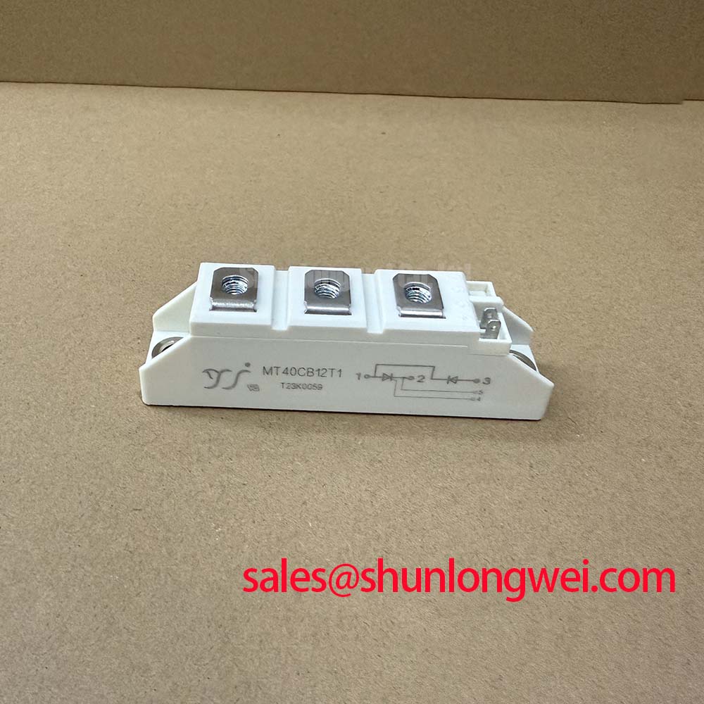
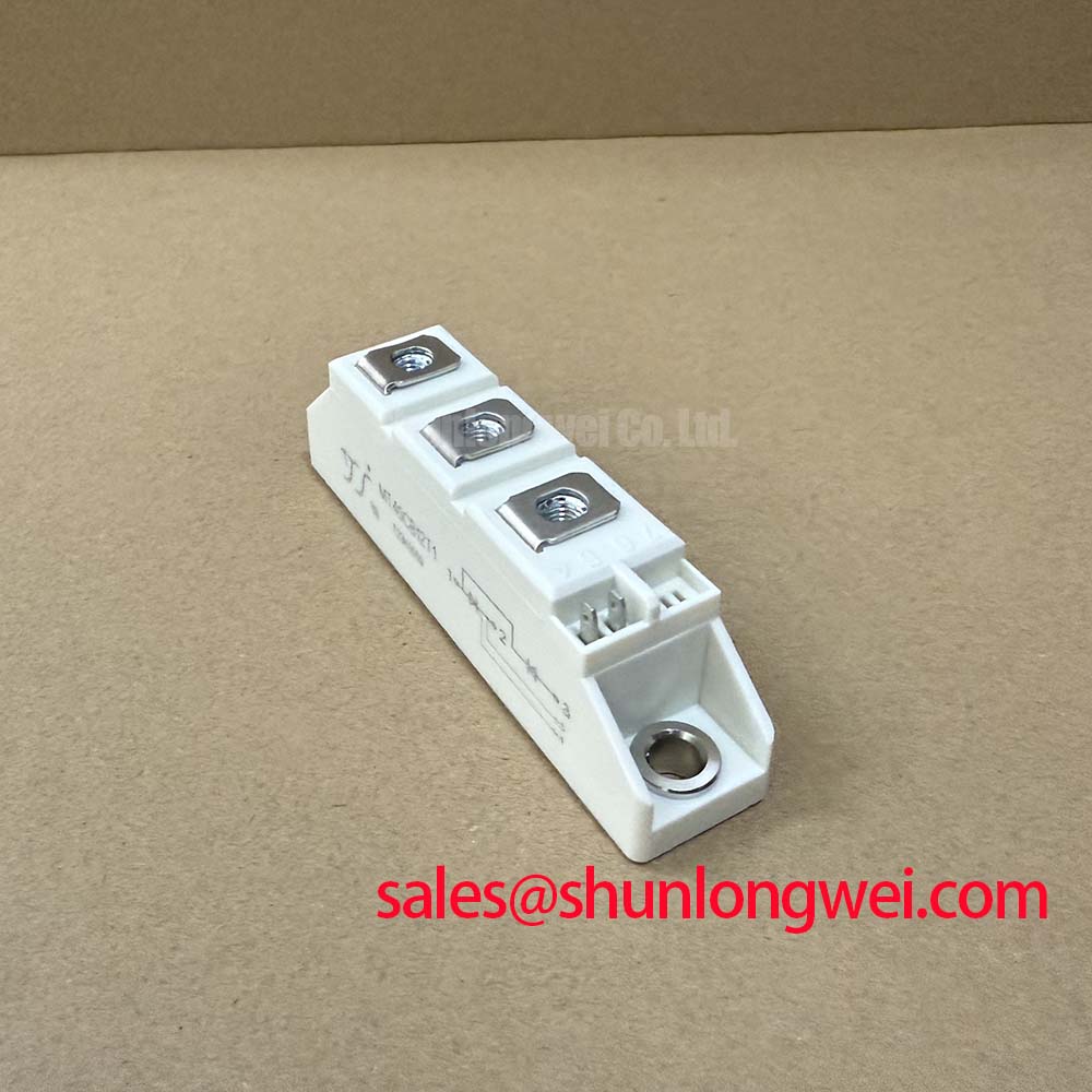
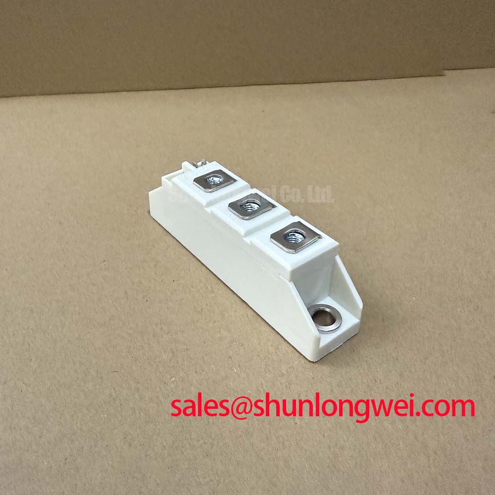
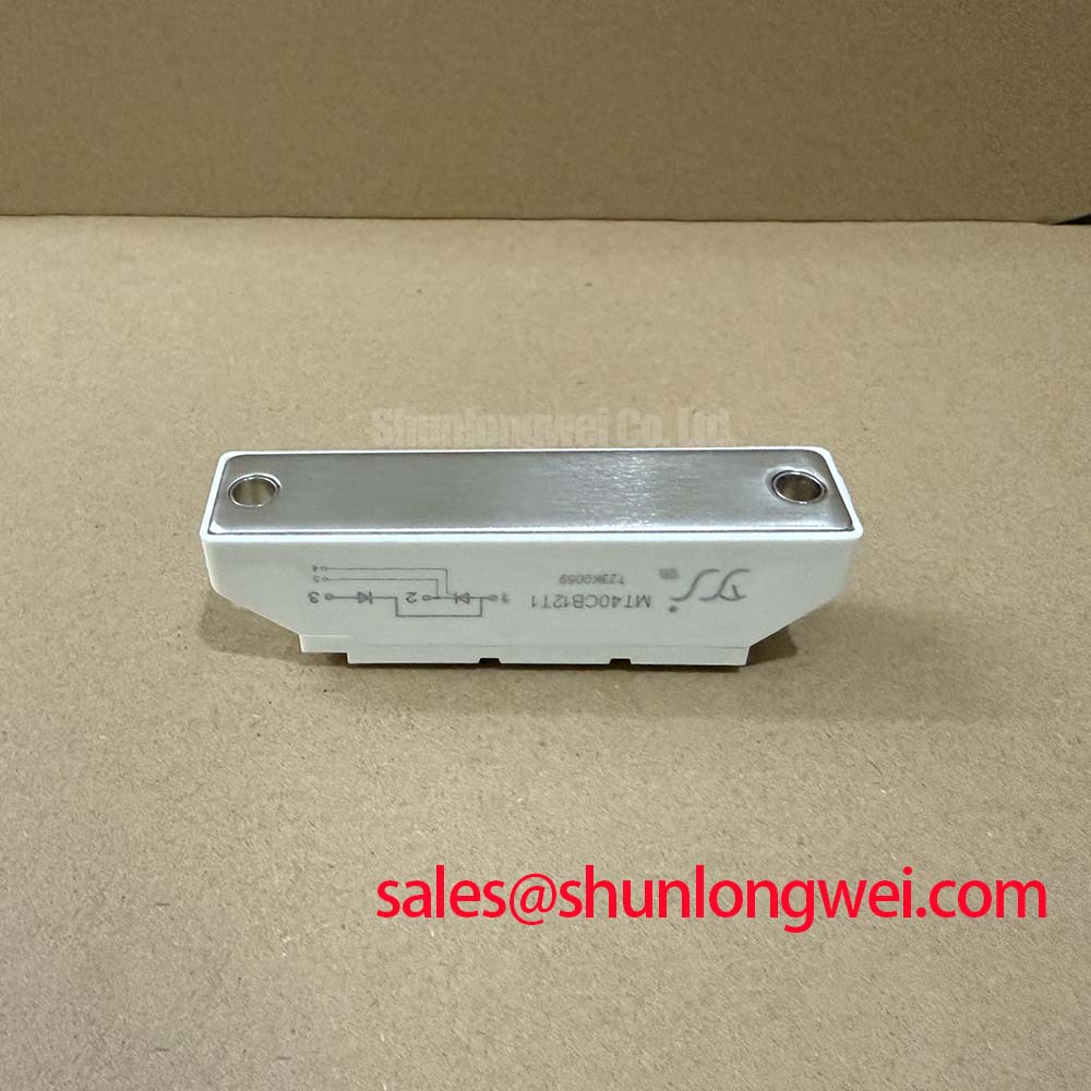
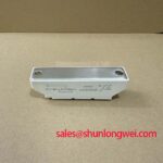
With the soft starter isolated and discharged, first verify that the installed MT40CB12T1 terminal arrangement, heatsink contact face, and nameplate ratings match the failed assembly before reconnecting any control wiring. The MT40CB12T1 from SanRex (Sansha Electric) is a thyristor and diode module specified at 1200 V VRRM and 40 A DC output current at Tc = 85°C. It is relevant to controlled AC power stages where the original circuit topology, terminal configuration, and thermal interface have been confirmed.
| Official Datasheet Specification | Value |
|---|---|
| Repetitive Peak Reverse Voltage, VRRM | 1200 V |
| DC Output Current, ID | 40 A at Tc = 85°C |
| Surge Forward Current, IFSM | 1000 A at 10 ms |
| Isolation Breakdown Voltage, Visol | 3000 V RMS for 1 minute |
| Thermal Impedance, Junction to Case, Rth(j c) | 0.33 °C/W |
| Operating Junction Temperature, Tvj | −40 °C to +125 °C |
In a high voltage three phase motor solid state soft starter, phase angle control is commonly assessed because it can reduce locked rotor current from the motor’s usual six to eight times rated current toward a lower controlled level. The actual current profile, acceleration duration, motor load, and bypass contactor transfer point remain system determined. The MT40CB12T1 official current rating is 40 A at a case temperature of 85°C; this is the electrical boundary to verify against the measured duty cycle, not a substitute for motor starting calculations.
Before fitting a replacement, inspect the upstream semiconductor fuse documentation and compare its published I²t characteristic with the starter manufacturer’s coordination requirement. The module’s official 1000 A, 10 ms surge forward current identifies a short duration surge rating, but it does not provide a fuse selection value or prove coordination with a particular feeder. Confirm conductor termination tightness, phase symmetry, and bypass contactor operation during controlled commissioning. A contactor that transfers late, early, or inconsistently can alter the thermal duty imposed on the controlled power stage.
For repair evaluations where the original assembly cannot be sourced, FRS200CA100 can be reviewed as a separate device option, but its terminal pattern, ratings, cooling interface, and circuit function require independent comparison with the original equipment documentation.
MT40CB12T1 Circuit Protection & Reliability: Calibrating Mechanical Mounting Torque Sequence and Thermal Contact
The specified 0.33 °C/W junction to case thermal impedance describes the thermal path from the semiconductor junction to the module case under the manufacturer’s stated conditions. It does not include grease condition, heatsink flatness, airflow, enclosure temperature, or the case to heatsink interface. As explained in this reference on thermal resistance and transient thermal impedance, each interface in the heat path contributes to the resulting temperature rise.
A Design Consideration is to clean the mating surfaces, apply a continuous thin thermal compound layer, and tighten mounting hardware progressively in an alternating pattern so the contact pressure remains even. Inspect the baseplate for rocking before electrical energization. Mounting torque must follow the module documentation and the installed fastener specification; no torque value is confirmed by the supplied MT40CB12T1 data.
⚠️ Field Alert: Isolate all power and confirm stored energy is discharged before loosening power terminals or removing a heatsink mounted module.
The 3000 V RMS isolation breakdown voltage for 1 minute is an official dielectric withstand specification, not a statement of complete equipment insulation coordination or regulatory compliance. System designers should verify creepage, clearance, enclosure condition, and test procedures at the assembly level.
Assembly Integrity & Layout Architecture: Implementing Surge Energy Dissipation and Clamping Voltage for MT40CB12T1
Inspect incoming AC terminals, surge suppression parts, snubber components, and bus joints before assigning a failed module as the sole cause of a shutdown. A damaged MOV, open snubber capacitor, loose connection, or degraded fuse holder may contribute to abnormal electrical stress. For installations assessed against surge practices associated with IEC 61000 4 5, protection coordination should be verified at the equipment level because source impedance, installation category, cable routing, and the surge test plan determine the required response.
An Engineering Recommendation is to keep the high current path compact and mechanically secure to limit parasitic inductance during current transitions. MOV and RC snubber selection should be based on measured waveform behavior and the original schematic. Confirm peak voltage across the installed module during switching tests against the official 1200 V VRRM rating. Do not assume that a generic suppression network is suitable for every soft starter frame or supply arrangement.
Where the input rectification or auxiliary power section is under review, PK55FG120 is a related power device that can be evaluated within its own published limits. It should not be treated as an automatic circuit substitute for the MT40CB12T1.
Preventing Spurious Faults: Gate Trigger Current Dynamics Guidelines for MT40CB12T1
Do not assign a gate trigger current, gate pulse rise rate, holding current, or multipulse firing setting to the MT40CB12T1 from the ratings listed here. Those values are not included in the supplied official parameter set. The system integrator should verify the required gate drive conditions from the original module documentation and the soft starter control board design before applying firing pulses.
During a controlled fault investigation, compare the firing waveform and phase timing with a known good channel using suitable isolated measurement equipment. Uneven firing, delayed conduction, or unexplained heating may indicate a problem in the trigger transformer, gate wiring, control reference, snubber network, load circuit, or the power module itself. A Design Consideration is to review gate lead routing and return paths together, since noise coupled into a trigger circuit can create inconsistent firing behavior.
For broader context on switching losses, drive layout, and industrial power stage evaluation, see Unlocking Efficiency in Industrial Drives. That technical discussion supports system level analysis but does not alter the official MT40CB12T1 ratings stated above.