Content last revised on September 15, 2026
Transient Dynamics & Electrical Design: Preventing Localized Gate Hotspot Burnout on DFM900FXM18-A000
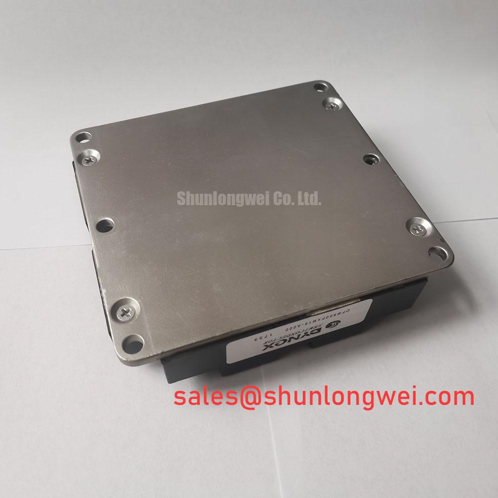
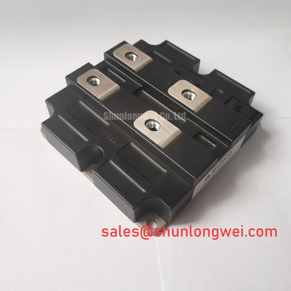
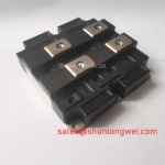
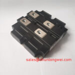
Before connecting the power circuit, verify the nameplate boundary of DFM900FXM18-A000 against the cabinet schematic, then inspect the power terminals, gate connections, thermal interface, and integrated NTC wiring for damage, contamination, or looseness while the equipment is isolated.
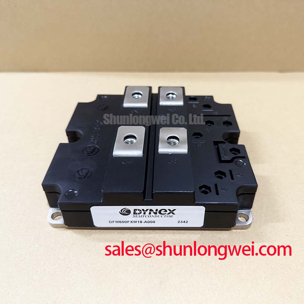
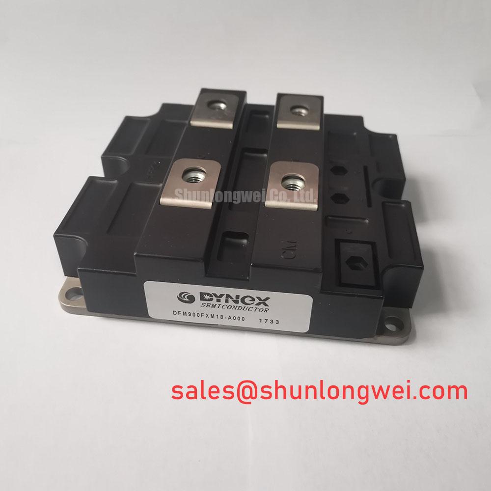
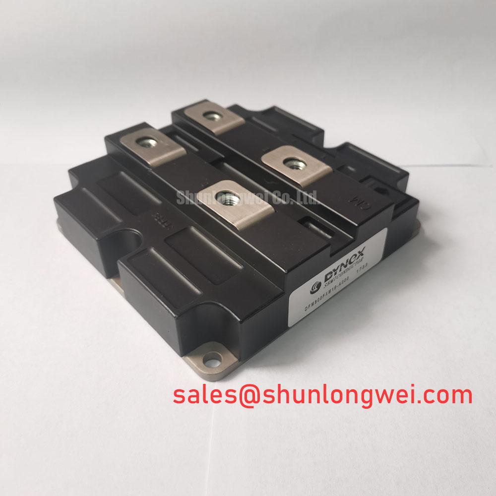
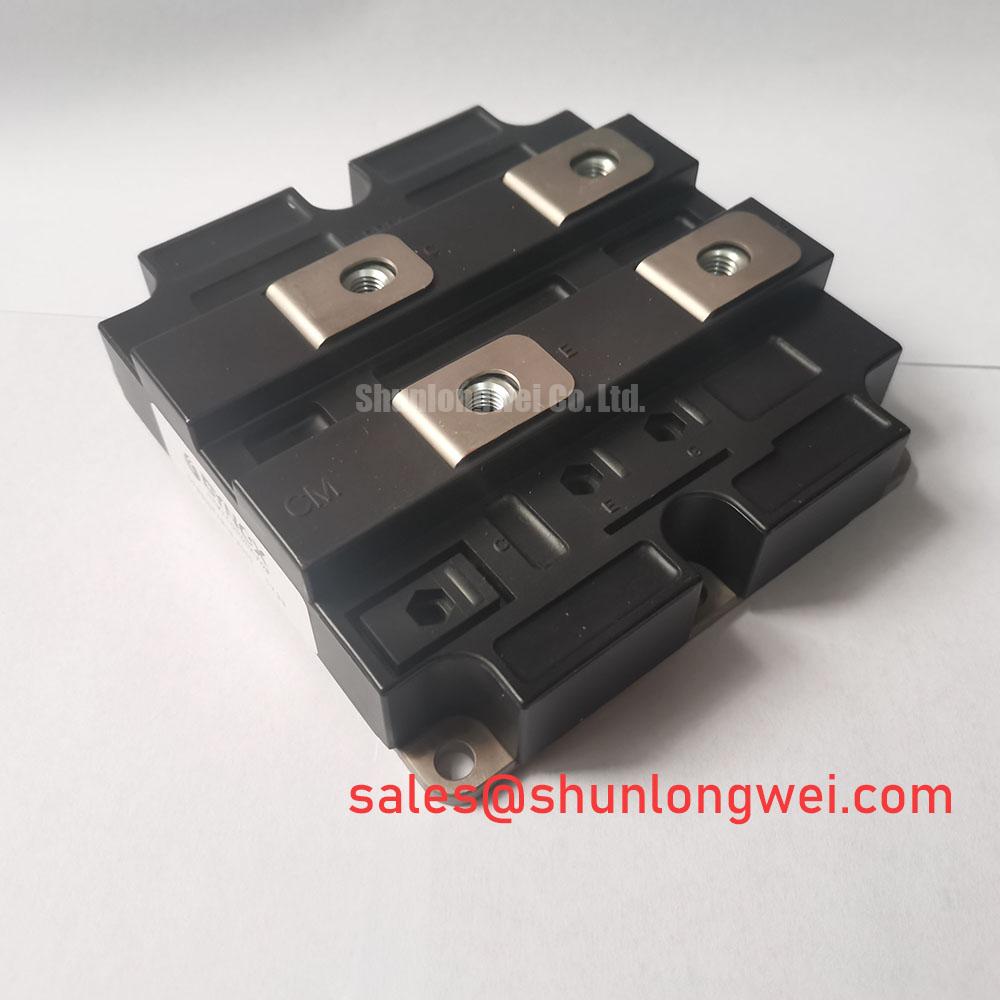
The Dynex DFM900FXM18-A000 IGBT module is published with an 1800V collector-emitter voltage rating and a 900A continuous collector-current rating under specified conditions. Its published electrical and thermal limits should be treated as the component identity, not as a complete soft starter system rating. The surrounding line supply, phase topology, protection coordination, cooling assembly, gate driver behaviour, and motor duty cycle must be evaluated by the system engineer.
| Official Datasheet Specification | Value |
|---|---|
| Collector-Emitter Voltage, VCES | 1800V |
| Continuous Collector Current, IC | 900A |
| Collector-Emitter Saturation Voltage, VCE(sat) | 2.1V typical at 900A |
| Gate-Emitter Voltage, VGE | ±20V |
| Total Power Dissipation, PTOT | 5000W |
| Junction Temperature Range, TJ | −40°C to +150°C |
| Thermal Resistance, Junction to Case, RTH(j-c) | 0.025°C/W |
| Integrated NTC Thermistor | Yes |
The numerical electrical and thermal values above apply under the respective datasheet conditions and should not be interpreted as unrestricted system operating conditions.
The ±20V VGE rating is the maximum specified gate-emitter voltage rating. It does not specify an approved driver supply, gate resistor, peak gate current, gate pulse rise time, pulse train sequence, or Miller clamp arrangement. Those values must remain system determined and should be checked against the original driver documentation and measured waveforms.
Terms such as gate trigger current, holding current, back porch current, and multi pulse latching belong primarily to thyristor triggering practice. They should not be assigned to DFM900FXM18-A000 without an applicable Dynex switching and gate charge specification. In an IGBT soft starter topology, the practical questions are whether the driver establishes a stable intended gate state, whether the gate return path is controlled during high current commutation, and whether collector voltage transients couple into the gate loop strongly enough to create unintended switching.
Design Consideration: keep the gate driver loop physically compact and give the gate emitter return a controlled, direct path to the module connection specified by the equipment design. This reduces susceptibility to parasitic inductance and Miller induced disturbance while the collector current changes. Oscilloscope checks should compare gate-emitter voltage and collector-emitter voltage during the actual turn-on and turn-off events, with probe placement selected to avoid creating misleading loop pickup.
The listed 2.1V typical VCE(sat) at 900A is useful for evaluating conduction loss behaviour under the stated test current, but it is not a guaranteed operating voltage for every junction temperature or switching condition. A rising measured on-state voltage can result from temperature, drive conditions, contact resistance, measurement location, or device degradation. Compare phase channels under equivalent load and use the system’s calibrated sensing method before drawing a conclusion.
The upstream fuse must be selected from the complete protection study, including the semiconductor manufacturer’s applicable overload and short circuit information, available fault current, cable impedance, coordination with contactors, and the fuse maker’s published I²t data. No fuse I²t rating is provided in the official information available for this module, so no numeric coordination value should be attributed to DFM900FXM18-A000.
💡 Pro Tip: Arrange the DC bus or phase conductors as a compact, symmetric current path where practical, then verify switching peak voltage margins by double pulse or equivalent system level testing under controlled conditions.
When a repair team is comparing an installed assembly with another high current Dynex format, DIM800DCM17-A can be reviewed as a separate device record. Any interchange decision requires confirmation of topology, terminal layout, driver compatibility, isolation arrangement, cooling interface, voltage class, current duty, and protection settings rather than a comparison of current ratings alone.
Assembly Integrity & Layout Architecture: Reverse-Recovery and Thermal Considerations for DFM900FXM18-A000
Inspect the mounting plane before tightening the module. Remove old thermal compound, check that the heatsink surface is flat and free from raised marks, and ensure that power busbars do not impose side load on the terminals. The official thermal resistance of 0.025°C/W junction to case describes the semiconductor-to-case path under specified conditions. It does not include the thermal interface material, heatsink, liquid plate, airflow, enclosure temperature, or temperature rise caused by neighbouring parts.
⚡ Safety Interlock Note: Isolate and discharge the complete DC link or AC source according to the equipment procedure before removing gate, NTC, or power connections.
Mounting torque, screw diameter, tightening pattern, and terminal torque are not stated in the supplied official parameter set. Do not apply a generic torque value as a product specification. Use the Dynex mechanical drawing or the original equipment service documentation for the exact fastening requirement. As a Design Consideration, an even cross pattern helps avoid uneven thermal contact, while the final torque remains dependent on the documented hardware and module base construction.
The provided specifications do not state diode reverse recovery peak current, reverse recovery time, soft recovery factor, or even an internal diode configuration. Therefore, values for IRRM, tRR, and recovery softness must not be inferred for this model. If the soft starter circuit uses an antiparallel diode, external freewheel path, clamp branch, or commutation diode, the system integrator should identify that item from the schematic and obtain its individual datasheet before estimating switching loss or conducted and radiated disturbance.
Design Consideration: reverse recovery stress is influenced by current before commutation, junction temperature, current slew rate, and bus inductance. A sharp current transition can increase voltage overshoot and excite ringing in the power loop. The corrective path is to examine the complete commutation loop, including busbar geometry, snubber placement, driver timing, and the actual diode or clamp device specification, then validate changes with voltage and current measurements.
In a high voltage three-phase motor solid-state soft starter, the power module should be assessed within the actual phase-leg arrangement rather than as an isolated current switch. A front end or auxiliary power stage may contain parts such as GD15PJX120F4S, but its role, ratings, and connection must be verified against the equipment schematic. It should not be assumed to be electrically interchangeable with the IGBT module or to define its reverse recovery behaviour.
The integrated NTC thermistor provides a temperature sensing element within the module assembly. Its presence is an Official Datasheet Specification. The control board must still verify sensor continuity, connector seating, input scaling, alarm logic, and the relationship between measured NTC temperature and the relevant protection threshold defined by the original system.
Field Diagnostics & Commissioning: Surge Energy Dissipation and Clamping Voltage in DFM900FXM18-A000 Topologies
Commissioning should begin with de-energised checks of phase-to-phase isolation, gate circuit continuity, NTC signal integrity, heatsink bonding, and the condition of surge suppression parts already fitted in the equipment. After these checks, controlled energisation with appropriate measurement equipment can reveal whether the intended gate sequence, line voltage waveform, and thermal feedback are behaving consistently across all phases.
The 1800V VCES rating is the maximum specified collector-emitter voltage rating of DFM900FXM18-A000. It is not a statement that a complete starter withstands a particular utility surge, installation category, insulation coordination level, or electromagnetic compatibility requirement. Protection against line disturbances is a system responsibility involving supply impedance, disconnecting devices, fuses, metal oxide varistors, RC networks, layout, control isolation, and the characteristics of every device connected to the phase circuit.
IEC 61000-4-5 is commonly used as a system-level surge immunity test framework. It does not provide a module-specific approval merely because an IGBT is installed in a tested enclosure. When evaluating MOV or RC snubber parts ahead of a switching branch, designers should use the equipment’s nominal line voltage, expected surge environment, clamp coordination, energy capability, temperature conditions, and failure mode requirements. The clamping voltage should be verified against observed device voltage, not assumed from an MOV catalogue value alone.
For fault investigation, record the command signal, gate-emitter voltage, collector-emitter voltage, line current, and NTC response at the same operating point. A recurrent overvoltage event may indicate an unsuitable clamp condition, excess stray inductance, a timing issue, load regeneration, or a measurement setup problem. The evidence should be reviewed as a set before replacing parts or changing the control strategy.
Gate insulation behaviour is influenced by electrical stress, temperature, and time. General discussion of negative bias temperature instability and quantum tunnelling describes mechanisms relevant to dielectric reliability research, but does not establish a service life, failure rate, or qualification result for this specific module. For equipment troubleshooting methods and broader power conversion context, see Future of Power Electronics.
The official junction range of −40°C to +150°C and 5000W total power dissipation should be used carefully. Total power dissipation is a datasheet limit under defined conditions, not a usable thermal budget for an assembled starter. The system must establish thermal performance through its own heatsink or cooling plate design, interface quality, airflow or fluid conditions, switching duty, and measured case and NTC temperatures.
Preventing Spurious Faults: Dynamic Voltage Sharing and RC Damping Guidelines for DFM900FXM18-A000
Spurious fault trips and unintended switching often require examination of the electrical environment rather than immediate attribution to the IGBT module. In series-connected switching positions, dynamic voltage sharing depends on device characteristics, gate timing, passive balancing elements, temperature distribution, and wiring symmetry. The supplied official data does not define whether DFM900FXM18-A000 is approved for a particular series stack or establish any balancing network value.
Engineering Recommendation: minimize parasitic loop inductance between the module, bus conductors, snubber network, and associated commutation components to reduce turn-off overshoot. The final RC damping network, series reactor selection, and gate control arrangement must be determined from the circuit’s measured ringing frequency, current profile, voltage margin, component losses, and thermal performance. Installing arbitrary resistor or capacitor values can shift stress elsewhere in the starter.
An RC snubber should be evaluated as part of a measured transient response. A waveform that appears to ring at the module terminals may be affected by probe grounding, lead placement, common mode noise, or bandwidth limitations. Use a measurement method appropriate to the voltage class and compare results with a known stable phase path where possible. If the system has multiple paralleled or series-connected branches, measure timing and voltage distribution during the relevant switching event rather than relying only on static resistance checks.
The 900A continuous collector current rating is an Official Datasheet Specification, while actual starter current can be nonuniform during motor acceleration, bypass transfer, stalled rotor conditions, and fault clearing. The control system should therefore be verified for current sensing integrity, gate command consistency, phase balance, and response to the integrated NTC signal. No surge current capability, repetitive overload duration, short circuit withstand time, or lifetime figure is included in the supplied official data, so those values should not be created during replacement planning.
For a repaired high voltage three-phase motor solid-state soft starter, retain the original protection architecture unless a qualified system review establishes a change. Confirm the module’s terminal assignment from the equipment drawing, verify gate polarity before energisation, validate cooling contact, and inspect switching waveforms under controlled load. These checks keep the 1800V, 900A Dynex DFM900FXM18-A000 within an evidence-based integration process rather than treating a single module rating as a complete system prescription.