

Content last revised on September 13, 2026
Full-Screen Primary Color AOI Screening: Stuck Sub-Pixels & Background Uniformity Audit
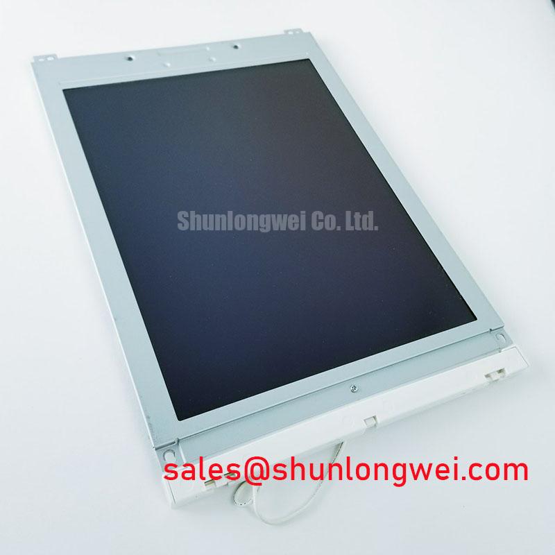
Run the first visual inspection with the panel installed on a stable, non conductive bench and connected through the equipment’s known good display path. Display full screen red, green, blue, white, black, and neutral gray test fields when the controller supports them. Observe the panel from a normal working angle and then inspect the surface using a 45 degree flashlight position with the display unpowered. This dark shadow method can reveal frame pressure, surface contamination, scratches, localized optical marks, and areas where a suspected backlight issue may be confused with a pixel or driver line defect.
A single fixed sub pixel, a narrow vertical line, or a persistent horizontal defect should be recorded by position and color rather than assigned to one cause immediately. Compare the symptom during a cold start, after warm operation, and with a known good signal source. If the defect follows the cable or controller, the display itself may not be the primary source. If it remains fixed at the same glass position, the engineer should compare the result with the original unit and verify the signal path using suitable test equipment.
Background uniformity should be checked at low, medium, and high image levels. A dark patch that changes with viewing angle may require separation of optical non uniformity from backlight distribution. A bright patch that remains visible on a black field may require inspection of frame loading, gasket compression, and the mechanical flatness of the bezel. The supplied factory information does not state an allowable mura limit, pixel defect class, or optical uniformity value for this model, so acceptance criteria should come from the original equipment manufacturer’s maintenance specification.
When the host system uses PWM backlight control, the controller engineer should verify the actual switching frequency and duty cycle linearity against the display and driver documentation. A practical system design consideration is to evaluate a PWM range around 200 Hz to 1 kHz only when it is compatible with the installed backlight driver, camera based inspection equipment, and human viewing conditions. Audible noise, visible flicker, beat patterns, and unstable brightness should be checked at both the minimum and maximum commanded levels. These are integration checks, not factory specifications for DMF-50383NF-FW.
Thermal Cycling Degradation of Polarizer Adhesives & Sealant Gasket Integrity
Before placing the display in a sealed operator station, inspect the perimeter gasket for cuts, compression set, oil contamination, and loss of adhesion. The gasket should contact the enclosure continuously without forcing the glass into a bowed position. Uneven bezel pressure can create localized optical variation and may also transfer mechanical stress into the panel assembly. Use the original enclosure geometry as the reference because the available factory parameter set does not confirm a particular gasket material, adhesive system, sealing grade, or environmental certification.
Low temperature operation can increase liquid crystal viscosity and lengthen visible gray to gray transitions. This effect should be measured using the actual image pattern, controller timing, and backlight state used by the machine rather than inferred from a general LCD value. For equipment exposed to sub zero conditions, designers should verify cold start behavior, image readability, touch response if applicable, and recovery time after the enclosure reaches its normal operating condition. A heater strip or controlled warm up sequence may be considered only after the thermal design team confirms that it does not create local hot spots or condensation risk.
The requested range of −30°C to +85°C must not be treated as an official operating or storage rating for this model because that rating is not present in the supplied factory data. It may be used as a proposed environmental test envelope for an equipment level evaluation, provided the original documentation supports the test and the complete display assembly is monitored. Inspect for haze, edge lifting, discoloration, sealant separation, and image non uniformity after cycling. Any change should be correlated with temperature, humidity, enclosure pressure, and mounting stress.
Condensation control is especially important in outdoor cabinets and process areas. The enclosure should manage moisture entry, internal dew formation, and pressure equalization without directing liquid toward the display connector. Maintenance Note: isolate power before disconnecting the display cable and inspect the gasket and cabinet airflow during scheduled service. A periodic record of startup image quality, brightness setting, fan condition, and seal condition provides useful field evidence without assigning an unsupported service life or failure rate.
For a potential Zone 2 hazardous-area operator station, the display should be evaluated as one part of the certified enclosure and control assembly. This module should not be described as independently carrying hazardous-area approval, ingress protection, EMC approval, or explosion protection unless the relevant complete system documentation states so.
Aluminum Heat Spreader Sizing & Thermal Interface Placement along Narrow Display Edges
Thermal management begins with identifying every heat source near the display perimeter, including the backlight driver, controller electronics, cabinet power supply, and adjacent motor control equipment. The supplied information does not confirm whether this model uses an LED or another backlight architecture, nor does it publish a backlight current, efficiency value, MTBF, L70, or B50 figure. Claims such as 50,000 hour MTBF or a defined LED depreciation curve therefore require a manufacturer datasheet or qualified test report before they are used in procurement or reliability calculations.
An aluminum spreader rail may be considered when a measured thermal map shows localized heating along a narrow edge. Its role is to distribute heat into an approved mechanical path while avoiding direct pressure on the glass, polarizer, flexible circuits, or optical layers. The interface should be continuous where specified by the equipment design, free from trapped debris, and mechanically compliant enough to accommodate differential expansion. The system engineer must determine rail thickness, contact area, fastening method, and thermal interface material after measuring the enclosure temperature and the display assembly’s permitted limits.
Do not place a conductive rail across exposed contacts or flexible cable folds. The display should remain supported in the same planes used by the original assembly, with fastening force distributed evenly around the frame. If a spreader is added during a retrofit, compare the image before and after tightening at black, white, and gray fields. A new bright edge, dark corner, or band can indicate altered mechanical loading rather than a thermal improvement.
Cold operation should be assessed together with heat removal. A heater can reduce startup response delay, but a poorly positioned heater may produce a thermal gradient across the panel and accelerate adhesive or sealant stress. Designers should measure the display surface, frame, and nearby air temperature during startup and steady operation, then verify image response and optical uniformity under the real enclosure airflow. The panel’s official operating range and response time remain documentation controlled values and should not be replaced by generic LCD assumptions.
General industrial design practice favors minimizing heat concentration and preventing direct thermal shock to the glass. It does not establish a model specific maximum temperature or lifetime for DMF-50383NF-FW. Reliability decisions should be based on the original Kyocera / OPTREX documentation and equipment level validation.
Radiated Emissions Compliance via Backplate Multi Point Star Grounding
Start EMC troubleshooting by separating display image defects from the noise source. Capture the same image pattern with the variable frequency drive disabled, operating at representative switching conditions, and isolated from the display cable where the equipment architecture permits. Pixel jitter and horizontal bands can arise from signal integrity, cable routing, grounding, power conversion, controller timing, or display faults. A symptom should therefore be compared with a known good cable and signal path before any component level conclusion is made.
For an LVDS or FFC based system, the integrator should verify the actual interface type and pin assignment from the original panel documentation. Do not assume a generic LVDS voltage, connector orientation, cable length, shielding arrangement, or power sequence for this model. Route high speed display wiring away from motor drive conductors, maintain the intended return path, and avoid unnecessary loops. A 360 degree shield termination may be considered where the enclosure and cable construction support it, but the termination method must be compatible with the equipment’s protective bonding and insulation design.
Backplate grounding should be treated as an enclosure level EMC design consideration rather than a guaranteed property of the LCD module. A controlled star or multipoint bonding arrangement can be evaluated to reduce common mode current, while common mode ferrite suppression may be considered when measurements show cable borne interference. Component selection and placement should follow conducted and radiated emission testing on the completed HMI assembly. The LCD module itself must not be represented as independently certified to CISPR Class A or Class B.
Use an oscilloscope or suitable differential probe to compare the display clock and data quality at the controller output and at the panel input. Check overshoot, ringing, common mode movement, and timing disturbance under the actual motor drive load. If a suspected insulation or discharge issue exists in a high voltage neighboring assembly, consult references such as Partial Discharge Detection in High Voltage Power Modules and Silicone Gel Encapsulation for High Voltage Insulation; these subjects concern surrounding power insulation and are not factory specifications for this LCD module.
Detailed enclosure bonding, shield termination, cable filtering, and motor drive separation can be reviewed alongside the Industrial Display & HMI Solutions engineering guide. Final acceptance should use the original system limits, the required safety documentation, and measured performance of the complete operator station.