

Content last revised on October 15, 2026
On Board Charge Pump Versus External DC to DC Negative Bias Supply Ripple Suppression
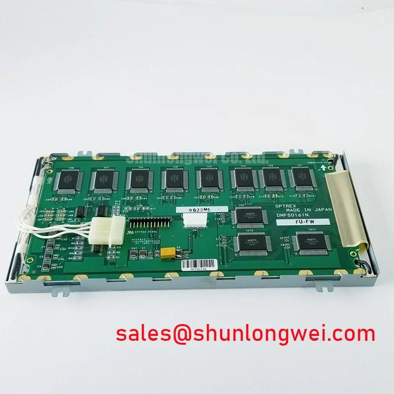
When a monochrome panel shows unstable contrast, I first separate the display interface problem from the bias supply problem by observing the panel’s contrast response while the host system moves through its normal temperature and power states. The DMF50161N is identified as an FSTN/STN monochrome passive matrix LCD panel, but the supplied product baseline does not define an internal charge pump, a dedicated negative bias converter, a CCFL interface, or an LED backlight circuit. Those functions must therefore be treated as system level integration points rather than assumed features of the panel.
A host design may generate the liquid crystal bias through an onboard charge pump or an external DC to DC supply. This choice affects ripple coupling, startup behavior, and contrast stability. As a Design Consideration, technicians should monitor the positive and negative display rails at the panel connector during power up, screen refresh, and backlight transitions. Ripple that follows the pixel clock or backlight control signal can point toward grounding, converter layout, or decoupling interaction rather than a defective LCD cell.
The proposed engineering focus for a negative bias rail in the range of minus 15 V to minus 24 V, with ripple discussed at a low tens of millivolts peak to peak, is not an official DMF50161N rating. It is a system evaluation boundary that must be taken from the original panel documentation and host circuit. A thermistor based compensation network may be evaluated where contrast changes across a wide temperature range, but its curve, placement, and control authority remain system determined. The technician should compare contrast at cold start and stabilized temperature while recording the actual rail waveform.
If the original terminal uses a high voltage fluorescent backlight, the cold strike circuit requires separate safety treatment. A suggested Design Consideration is to review the transformer, ballast, insulation system, creepage, clearance, and corona behavior around the high voltage nodes. The commonly encountered 1200 V to 1600 V RMS cold strike range belongs to a backlight subsystem evaluation, not to the published electrical identity of the DMF50161N. The backlight technology and drive requirements should be verified from the equipment service documentation before applying power.
4 Bit and 8 Bit Digital Parallel Bus Timing: Frame Sync, Line Pulse and Shift Clock
For a passive matrix display, timing faults are best isolated by comparing the frame sync signal, line pulse, and shift clock at the panel connector against a known good operating cycle. The design may use a 4 bit or 8 bit parallel path, depending on the host implementation. The available baseline does not assign a confirmed bus width or pin by pin timing table to the DMF50161N, so the original interface drawing remains the controlling reference for signal naming and polarity.
Frame sync, often identified as FLM, establishes the beginning of a display frame. The line pulse, often called LP, separates row transfer events, while the shift or clock signal, commonly identified as CP, advances data through the panel interface. When a panel shows shifted characters, partial rows, or unstable contrast, inspect the relationship between these signals rather than changing the display bias immediately. An oscilloscope comparison should include signal order, edge quality, idle state, and the timing relationship between data and clock.
Power sequencing deserves equal attention. The host should establish the required logic supply and control state in the order specified for the original assembly, then enable the display drive and backlight according to that system sequence. Applying a signal while the panel supply is absent can create unwanted DC conditions at the liquid crystal interface. The risk is especially relevant when a replacement panel is connected to legacy logic with different reset behavior or output enable timing.
At low temperatures, liquid crystal response can become slower because viscosity changes with temperature. This is a Design Consideration for sub zero equipment operation, not a confirmed performance rating for this model. Engineers evaluating a protection relay or SCADA console should check character settling, frame stability, and readability during cold startup rather than judging compatibility from the connector alone. Data format alignment also matters: JEIDA and VESA naming conventions are primarily associated with digital display links and should not be applied to this parallel passive matrix interface without an actual interface conversion stage.
💡 Pro Tip: Keep the clock and data paths referenced to a controlled return path and compare their relative arrival at the panel connector, because unequal routing can increase visible timing errors even when the host controller reports normal operation.
Transflective and Reflective Polarizer Aging Under Industrial Illumination
When an older monochrome terminal loses readability in bright surroundings, inspect the optical stack as a complete assembly rather than treating contrast loss as an immediate logic failure. FSTN and STN panels depend on the interaction between the liquid crystal layer, polarizers, ambient light, and any installed backlight. The DMF50161N baseline identifies the display as monochrome passive matrix, but it does not establish a confirmed transflective construction, polarizer material specification, ultraviolet exposure rating, or backlight type.
Reflective readability can change after prolonged heat, ultraviolet exposure, chemical contact, or pressure at the bezel. Iodine based polarizer aging is a general industry mechanism that may appear as uneven darkening, fading, color shift, or reduced contrast under strong ambient illumination. Adhesive bubbling or localized haze can produce similar visual symptoms. A practical inspection compares the affected area under controlled ambient light and then with the approved backlight state, allowing the engineer to distinguish optical degradation from a drive waveform problem.
For equipment such as a high voltage substation protection console or SCADA dispatch terminal, the enclosure window, front bezel, and service environment influence the result as much as the panel itself. UV exposure through an uncovered window, cleaning chemicals, and heat trapped behind the front frame should be recorded during replacement assessment. A compatible mechanical substitute must preserve the viewing aperture and connector orientation; optical appearance alone is not sufficient evidence of electrical interchangeability.
Where a legacy assembly uses a fluorescent backlight, transformer corona and cold striking behavior should be assessed separately from the LCD cell. The 1200 V to 1600 V RMS range is a Design Consideration for evaluating a possible high voltage backlight circuit, not an official rating assigned to this product record. Maintain the original insulation strategy and use the equipment manufacturer’s documented clearances. Do not connect an unverified high voltage backlight source to the panel.
For a same size or same resolution comparison, engineers may review LM64P701 as a separate reference model. Similar display appearance does not establish drop in compatibility; connector pinout, timing, bias requirements, viewing area, and mounting features still require a direct comparison.
Bezel Mechanical Frame Clamp Uniformity and Gasket Pressure Distribution
Missing rows or columns that change when the bezel is touched should be investigated at the mechanical interface, especially where an elastomeric zebra strip connects the glass assembly to the host circuit. Alignment, compression uniformity, frame flatness, and vibration history all affect contact stability. The DMF50161N product baseline confirms a standard form factor but does not provide an official gasket pressure specification, connector compression value, or mounting tolerance.
The supplied engineering focus cites 0.2 MPa to 0.3 MPa as a mechanical pressure evaluation range. This is a Design Consideration for a bezel and zebra connector assembly, not a factory specification for the DMF50161N. In practice, the engineer should use the original frame design and gasket geometry, then verify that the glass is supported without point loading. Excess compression can distort the cell or create localized optical marks, while insufficient compression can allow intermittent rows during vibration.
During service, inspect the frame for twist, displaced cushions, contamination, and uneven fastener loading. A row or column fault that changes with gentle frame pressure may indicate contact alignment or oxidation, but it should be confirmed by controlled continuity and signal checks rather than assigned to one cause. Cold operation can increase mechanical stiffness and slow liquid crystal response, so the panel should be evaluated across the equipment’s actual temperature range.
For replacement planning, record the display opening, visible area, connector exit position, frame thickness, and screw or clip locations before removing the existing unit. The host enclosure may be suitable for the standard form factor while still creating interference at the bezel or cable bend. Designers evaluating industrial HMI equipment can also consult Industrial Display & HMI Solutions for broader enclosure and interface considerations.
Color management references such as the sRGB Standard Color Space are not directly applicable to a monochrome passive matrix panel, while the HDMI protocol is relevant only when an external controller or converter is present. Neither reference changes the confirmed product category or establishes an interface feature for this model.