

Content last revised on October 6, 2026
Industrial Bezel Fit and Mounting Pressure
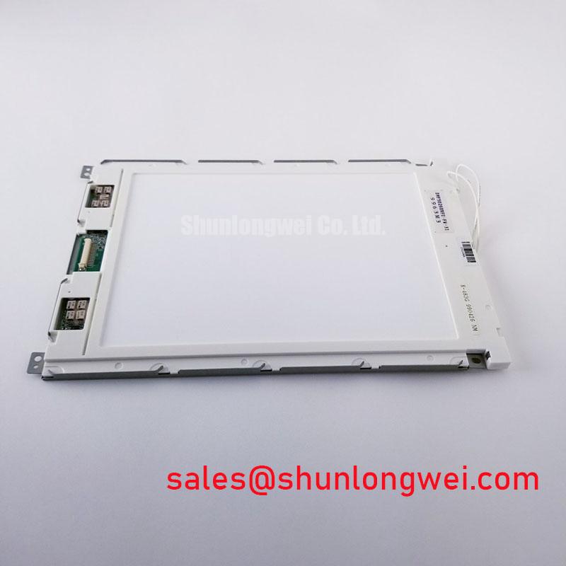
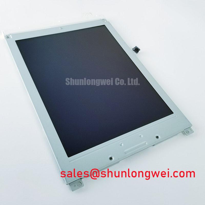
Start a replacement assessment at the enclosure, not at the display connector. Record the installed module’s overall outline, visible area, mounting-hole positions, connector clearance and cable exit path. Compare those measurements with the drawing for DMF50260NFU-FW-27 and with the removed assembly. A matching visible image area alone does not establish mechanical compatibility: the bezel may obscure the display, a cable may meet the chassis, or mounting points may load the module unevenly.
Before tightening the assembly, check whether the chassis is flat and whether its supports contact the intended mounting surfaces. As a Design Consideration, uneven clamping pressure can contribute to localized brightness or contrast irregularities on an LCD. If a dark patch appears after installation, compare the image with the module supported outside the bezel under otherwise unchanged operating conditions. That comparison helps distinguish a mounting-related symptom from an issue already present in the display or its drive path.
Do not infer a screw size, torque limit or gasket compression target from the product category. Use the original mechanical drawing and the equipment manufacturer’s assembly instructions. The same applies to enclosure sealing: a panel’s mechanical fit does not establish that the completed terminal meets a particular moisture or salt-exposure requirement.
Backlight Supply and Dark-Screen Diagnosis
A blank terminal does not, by itself, identify a failed LCD. With the equipment isolated, inspect the display cable and its connector seating. After restoring power under the service procedure, determine whether image data is present but illumination is absent. A faint image visible under external light can direct attention toward the backlight supply or control path; an entirely absent image still calls for checks of panel power, signal delivery and startup sequencing.
The available factory information identifies DMF50260NFU-FW-27 as a TFT-LCD display module but does not identify its backlight source, driver topology, supply voltage or current requirement. The system integrator should verify those items from the original panel documentation and the host equipment schematic. Measure the relevant supply at the connector under the conditions specified by that documentation, then compare enable and dimming signals with a known-good signal path where one is available.
If illumination starts and then drops out, observe the driver’s input, control signal and any documented fault output during the event. A protection response, an intermittent connector or an unstable supply can produce similar visible symptoms. Treat an open-load or short-circuit indication according to the installed driver’s documentation; neither protection behavior nor a fault-output pin can be attributed to this panel without its circuit information.
For a longer discussion of enclosure and signal-path checks, see Industrial Display & HMI Solutions. On this module, the immediate service task remains narrower: identify the installed backlight circuit, confirm its specified operating conditions and isolate the point at which illumination is lost.
Dimming and Display-Interface Verification
Once stable illumination is available, test brightness control through the host equipment’s normal range. Watch for visible fluctuation, abrupt brightness changes or a screen that extinguishes before the control reaches its intended endpoint. As a Design Consideration, dimming performance depends on the complete control and driver arrangement, not on the LCD model name alone. The original panel and equipment documentation should determine the control method and acceptable signal conditions; system testing should establish whether the installed combination behaves correctly.
Keep the image-data path separate from the backlight investigation. A lit panel with no usable image calls for checks of connector orientation, cable condition, panel supply and the host’s startup sequence. If an image appears only intermittently, inspect the connector contacts and observe the specified interface signals during the failure. Do not assign a TTL or LVDS pinout, timing margin or power-up delay to DMF50260NFU-FW-27 without its original interface specification.
Field alert: Power down the equipment before disconnecting or reseating the display cable.
For procurement and repair assessment, retain the complete suffix FW-27 when matching the installed label to documentation. A similar base model is not enough to confirm connector placement, interface wiring or backlight requirements. The decision should rest on the full part number together with the host equipment’s electrical and mechanical requirements.
Temperature, Optical Symptoms and Enclosure Assessment
When a display complaint varies with temperature, record the conditions under which it occurs before attributing it to the panel. Check whether the image changes uniformly, whether only the backlight changes, and whether the symptom follows a particular cable position or enclosure state. Cold-temperature image response and heat-related optical changes are useful diagnostic considerations, but no operating-temperature range, response time, contrast ratio or lifetime figure is established here for DMF50260NFU-FW-27.
Inspect the viewing surface and perimeter for visible damage, contamination or signs of pressure. Compare the displayed image at normal operating brightness with the panel outside any suspect bezel load, if the service procedure permits. An apparent contrast problem can be affected by viewing angle, ambient light, host image settings or illumination; record those conditions alongside the symptom rather than assigning a single cause from appearance alone.
A marine radar or navigation bridge console is a possible compatibility assessment example, not a confirmed application or environmental rating for this module. Before considering that installation, the equipment team should verify the original panel’s optical and temperature specifications and assess enclosure sealing, sunlight readability and exposure requirements at system level. For the immediate repair, close the comparison with documented fit, interface, supply and backlight requirements for the exact installed part.