


Content last revised on October 10, 2026
Cold-Start Response Time Viscosity Damping across Sub-Zero Machine Environments
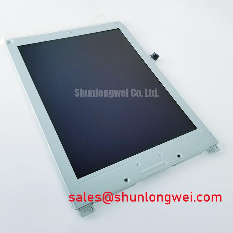
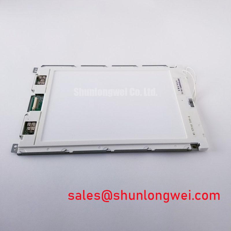
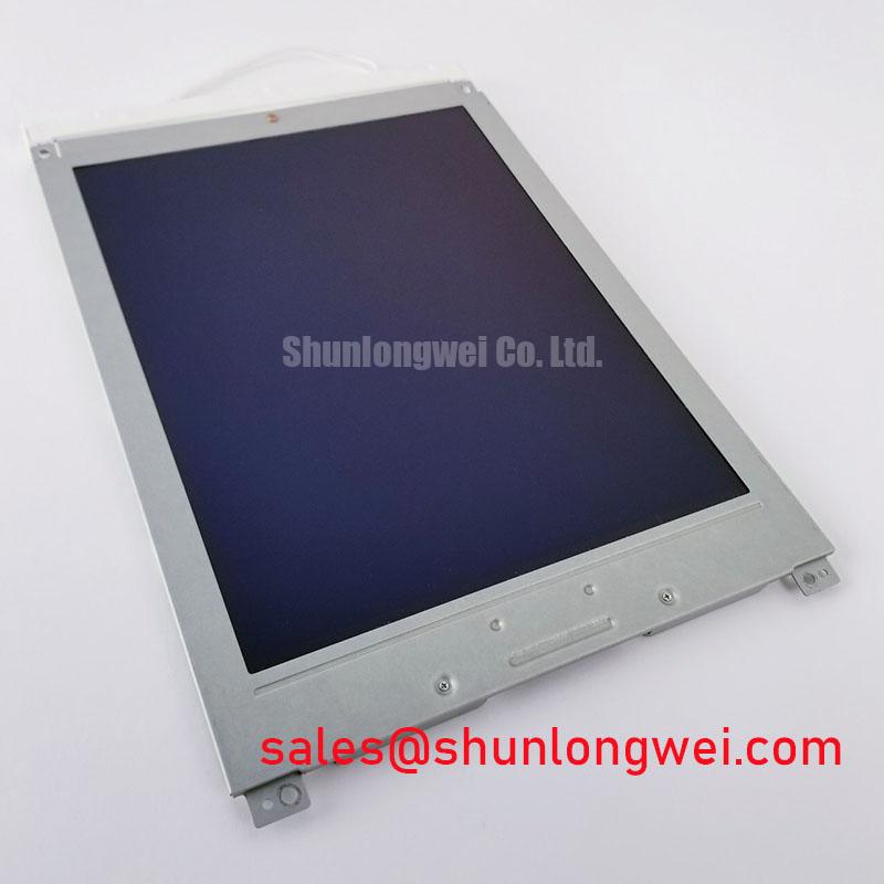
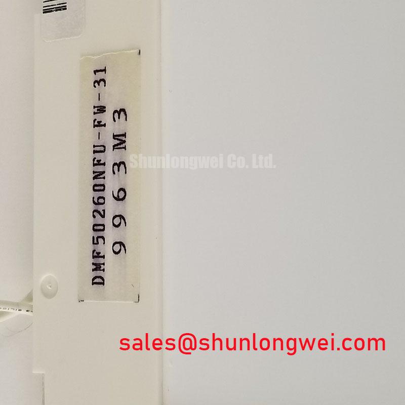
The Kyocera / OPTREX DMF50260NFU-FW-31 is an industrial LCD/HMI panel identified within the FSTN / STN monochrome passive-matrix category. Its decoded baseline identification is a starting point for replacement assessment, not proof of electrical interchangeability. The exact suffix matters when comparing the panel, host electronics, cable assembly, and enclosure.
Compare the cold-start image with the warmed-up image before changing the contrast setting on a DMF50260NFU-FW-31; record whether characters respond slowly, lose contrast uniformly, or show localized optical defects. These observations separate temperature-dependent display behavior from supply instability and mechanical stress without treating any single symptom as a diagnosis.
Observe repeated character transitions during a controlled cold start while keeping the test pattern and viewing position unchanged. Design Consideration: lower liquid-crystal temperature can slow optical transitions, making a correctly addressed image appear sluggish or leave temporary trails. Compare the behavior during warm-up before attributing it to the controller or increasing contrast bias.
Separate transition speed from static readability. A panel that eventually displays stable characters presents a different troubleshooting problem from one with persistent patches, uneven background shading, or defects that remain fixed relative to the viewing surface. Examine the exterior optical stack under consistent illumination for discoloration, surface damage, and visible separation. Do not infer polarizer chemistry or adhesive construction from appearance alone.
Design Consideration: ambient-light contrast depends on the installed optical arrangement, viewing direction, and enclosure window. Evaluate readability with the original window fitted, because surface reflections can obscure characters even when the display drive is stable. Antiglare or antireflection treatments on an enclosure window require separate assessment; they are not established features of this model merely because it serves an industrial HMI role.
Record temperature at a representative location near the panel rather than relying only on cabinet air temperature. If the host incorporates temperature-dependent contrast control, compare its sensor response with the observed image transition. The Industrial Display & HMI Solutions resource provides broader integration context for planning environmental checks; acceptance limits should follow the equipment requirements and applicable component specifications.
Cold-Cathode Fluorescent Lamp High-Voltage Strike Waveform & Open-Lamp Trip Threshold Tuning
Identify the installed illumination assembly before probing a startup waveform or altering a protection threshold. A CCFL troubleshooting procedure applies only to a confirmed CCFL-equipped assembly; the monochrome panel classification alone does not establish the backlight technology of DMF50260NFU-FW-31.
Design Consideration: in a confirmed CCFL system, capture the inverter enable signal, supply behavior, lamp-current feedback, and fault output during the same startup event. Distinguish an unsuccessful strike from a successful strike followed by protection shutdown. The inverter documentation defines the appropriate measurement method and protection boundaries; generic ignition voltages and lamp-current settings are not substitutes for assembly-specific limits.
Use instrumentation suitable for the inverter output and its grounding arrangement. Probe loading can change the observed strike behavior, while inappropriate grounding can create an unsafe measurement path. Inspect connector seating, cable routing, and insulation condition before interpreting an open-lamp indication. A shutdown can involve the lamp circuit, inverter supply, feedback network, or protection logic rather than a single failed part.
Engineering Recommendation: preserve the documented open-load and short-circuit protection behavior while assessing the fault. Defeating shutdown to keep the display illuminated removes useful diagnostic evidence and can expose the assembly to uncontrolled electrical stress. Compare fault timing with a known-good, matching assembly where available.
Illumination and LCD contrast should also be evaluated separately. Reduced brightness does not establish polarizer degradation, and stronger illumination does not necessarily restore ambient-light readability. Check the displayed pattern with controlled external lighting to distinguish an illumination problem from an optical or contrast-drive problem.
On-Board Charge Pump vs. External DC-DC Negative Bias Supply Ripple Suppression
Trace the contrast-bias path from the host connector to its generating circuit before adding filtering or changing an adjustment range. Design Consideration: a charge pump and an external converter can respond differently to loading, startup, and switching interference. Neither architecture should be assigned to this panel without a matching schematic or electrical specification.
Measure bias behavior at the display connection while exercising different image patterns and host operating states. Correlate visible contrast modulation with the measured disturbance rather than assuming that all flicker originates in the bias supply. Probe return placement matters: a long measurement loop can capture interference that is not representative of the voltage across the intended circuit nodes.
For replacement assessment, compare the DMF50260NFU-FW-31 with the LM64P11 at the electrical, optical, and mechanical interface level. A candidate part number is not a verified direct replacement merely because it appears in the same sourcing comparison.
| Selection checkpoint | DMF50260NFU-FW-31 | LM64P11 comparison requirement |
|---|---|---|
| Manufacturer identification | Kyocera / OPTREX | Match the exact manufacturer and suffix documentation |
| Display classification | FSTN / STN monochrome passive-matrix LCD baseline | Compare optical mode and host rendering requirements |
| Electrical and physical specifications | Consult Datasheet: resolution, dimensions, pinout, supplies, timing, illumination, and temperature limits | Compare the corresponding specifications before substitution |
| Replacement status | Reference panel for the equipment assessment | Requires interface and enclosure validation |
Engineering Recommendation: assess filtering together with startup settling and the contrast-control circuit. Added capacitance can reduce a disturbance while changing sequencing or control response. Where temperature compensation exists, check sensor attachment and circuit behavior before modifying the bias network.
Data Setup & Hold Time Margin Verification on High-Capacitance Flat Ribbon Flex Cables
Capture data and clock signals at the receiving connector with the actual ribbon cable installed, then compare their relationship with the required interface timing. Design Consideration: cable capacitance, return-path discontinuities, and connector resistance can degrade signal edges and reduce the usable setup-and-hold window.
For a confirmed parallel interface, map frame, line, and pixel-clock functions from the connector definition before interpreting labels such as FLM, LP, or CP. Do not infer signal polarity, bus width, or sampling edge from a familiar acronym. Check startup and shutdown sequencing against the specified relationship between logic, bias, and display drive.
Pro Tip: Keep data and their sampling clock routed together with a continuous return path, then verify timing at the panel connector rather than relying on controller-side waveforms.
LVDS differential routing and JEIDA/VESA mapping belong only to an interface explicitly using those conventions; they should not be imposed on a parallel monochrome connection. The VESA official portal provides standards context, not evidence that this panel implements a particular interface. Likewise, gamma correction and nonlinear tone reproduction concern image rendering and should not be treated as remedies for missing timing margin or unstable contrast bias.
When evaluating compatibility with railway passenger-information equipment or cab-signalling displays, compare the existing controller, aperture, mounting points, cable exit, and qualification requirements. Mechanical fit alone does not establish suitability. Finish the assessment by checking text patterns, transition behavior, and fault recovery with the enclosure closed and nearby equipment operating, correlating any disturbance with captured signals before changing the panel or host circuitry.