
Content last revised on October 27, 2026
Incoming Inspection and Test Preparation for DP300B1200100742
- Isolate the equipment, verify DC-link discharge, and match the module terminal markings to the equipment schematic before taking cold-state measurements.
- Record diode-mode readings in both polarities across documented power-terminal paths, with external parallel paths disconnected where practicable.
- Check terminal screw engagement, washer seating, busbar alignment, and heatsink contact before applying assembly torque.
- Identify the specified insulation-test connections and limits before connecting a withstand tester; protect gate-drive electronics from unintended test voltage.
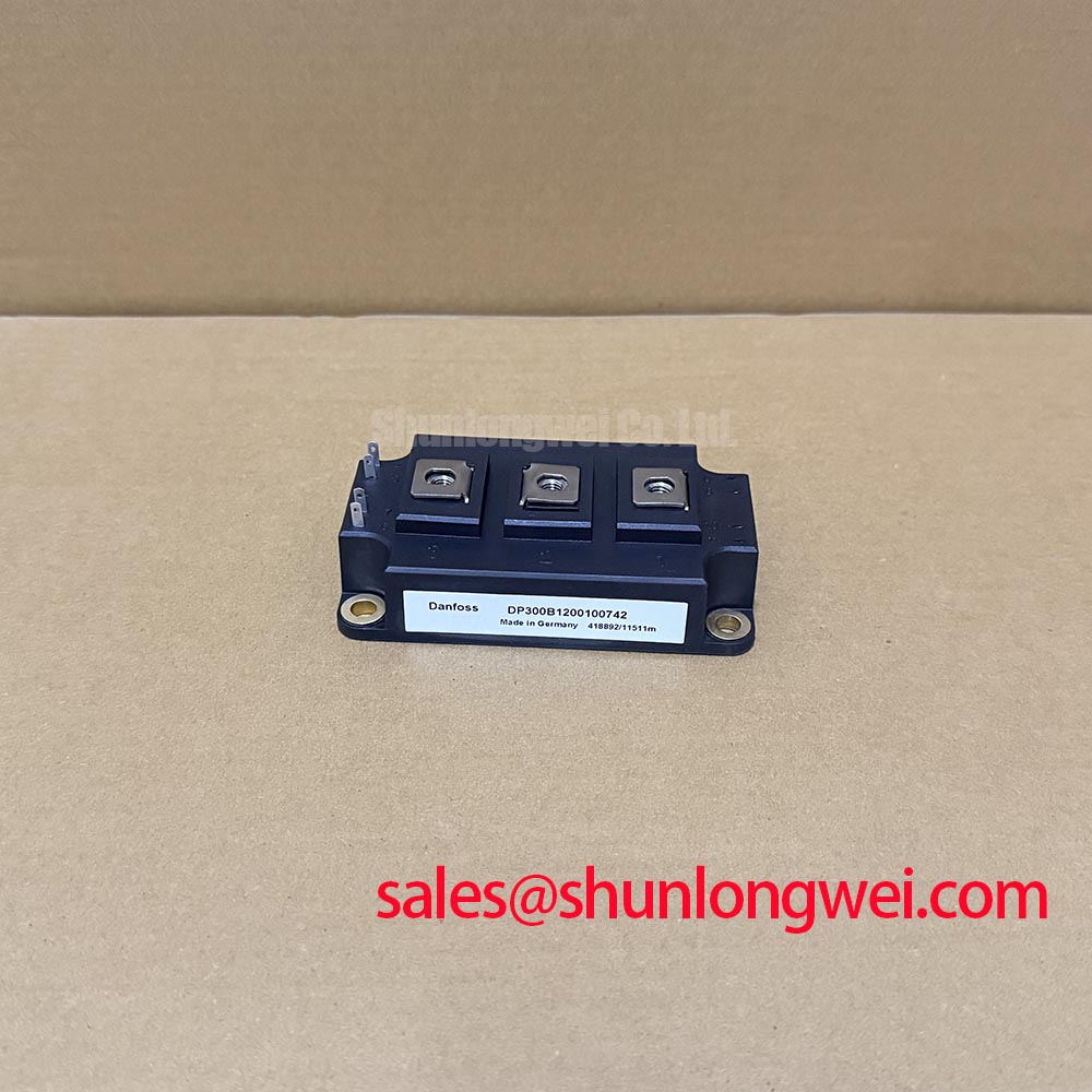
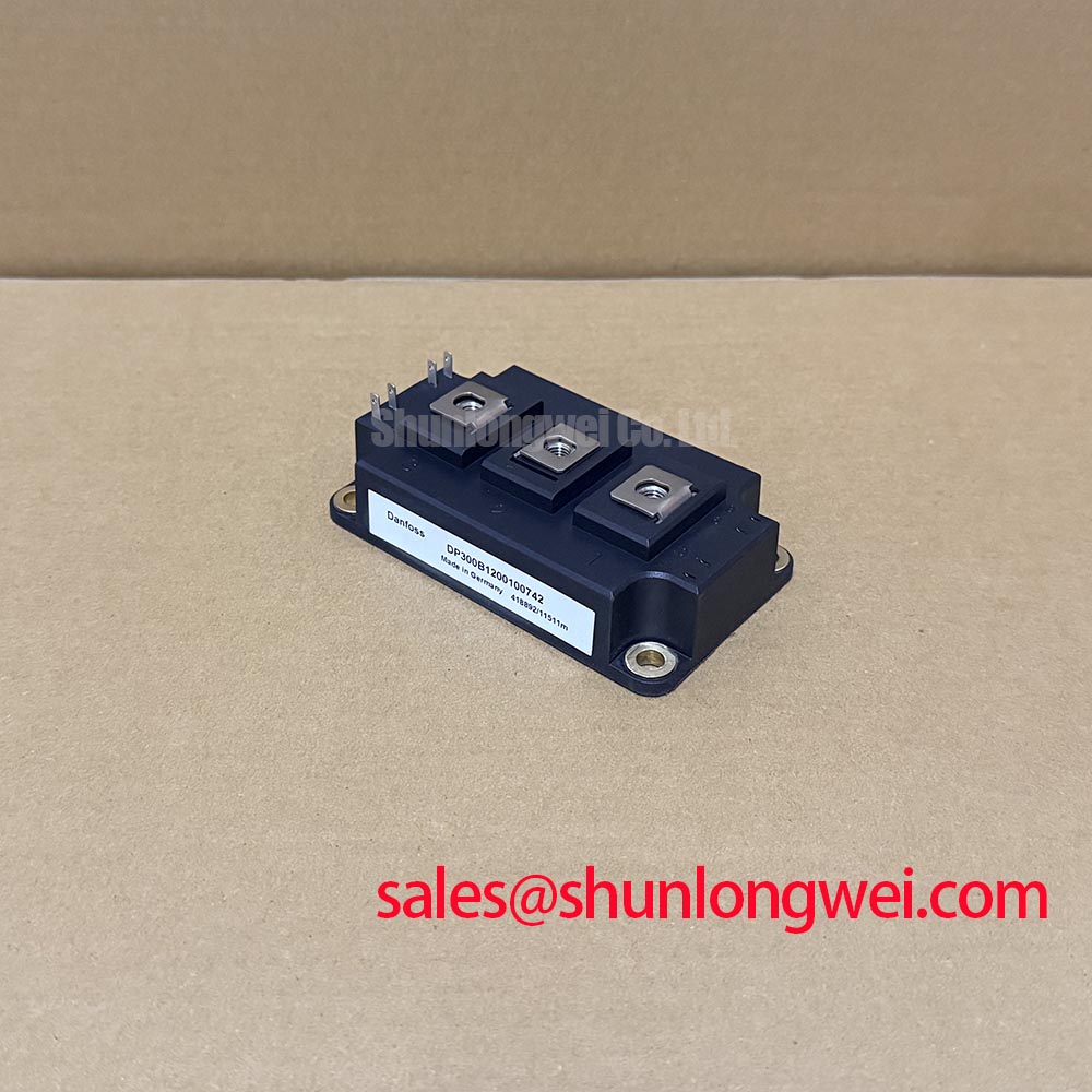
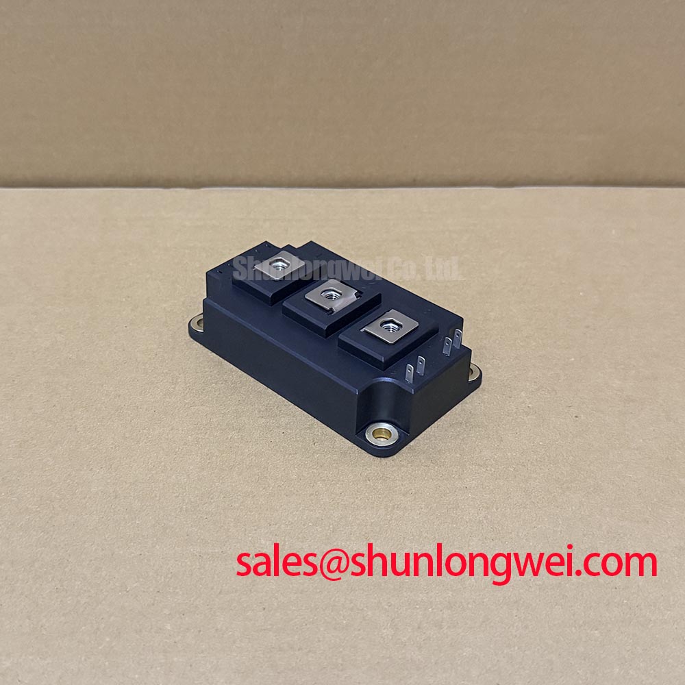
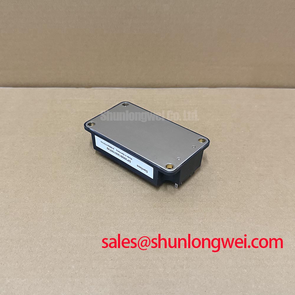
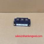
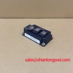
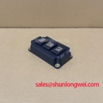
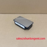
The DP300B1200100742 is a Danfoss IGBT Module with a CBI / Inverter Bridge topology designation. Incoming inspection should preserve the connection between terminal identity, measurement polarity, and test conditions: an isolated reading without that context is not a reliable acceptance criterion.
| Product identity | Supplied specification |
|---|---|
| Manufacturer | Danfoss |
| Model | DP300B1200100742 |
| Category | IGBT Module |
| Topology | CBI / Inverter Bridge |
| Brand designation | Danfoss Silicon Power |
| Series | Standard |
| Electrical ratings and assembly limits | Vces, Ic, insulation test voltage, dimensions, terminal assignments, screw engagement, and tightening torque: Consult Datasheet. |
💡 Bench Tip: Keep gate terminals under appropriate ESD protection and compare cold-state readings with a documented reference using the same instrument, polarity, and temperature conditions.
Transient Dynamics & Electrical Design: Terminal Screw Engagement Depth on DP300B1200100742
Check usable terminal thread depth against the complete busbar, washer, and screw stack before tightening the DP300B1200100742 connections. As a Design Consideration, a screw that bottoms out can produce apparent tightening resistance without establishing the intended contact pressure. Conversely, inadequate engagement can leave the connection mechanically vulnerable. Use the assembly drawing to establish the permitted hardware and engagement rather than selecting screws by external appearance.
Support the busbar so its contact face meets the terminal without being pulled into position by the fastener. Inspect washer seating and any specified locking arrangement, then apply the documented tightening procedure with a calibrated tool. Busbar misalignment can transfer bending loads into terminal attachments; this is a general assembly concern, not a statement about the module’s internal construction. Maintain the equipment drawing’s electrical clearances after installing covers, washers, and adjacent conductors.
For an intermittent connection complaint, examine contact witness marks, displaced hardware, discoloration, and movement at the external joint. A controlled connection-resistance comparison can help identify an abnormal interface, provided probe placement and temperature remain consistent. Such evidence should be considered alongside loading history and assembly condition rather than treated as proof of a single failure mechanism.
Engineering Recommendation: inspect the mounting surface and thermal-interface material separately from the power-terminal joint. Follow the specified flatness, material application, mounting sequence, and torque requirements; adding interface material does not correct a distorted mounting surface. Where pulse loading matters, use the applicable transient thermal impedance data and measured loss profile to evaluate peak junction temperature. Case temperature alone does not establish the junction temperature reached during a short pulse.
Field Diagnostics & Commissioning: PCB Symmetry Considerations for Dual IGBT in DP300B1200100742 Topologies
Trace each gate-drive return on the equipment schematic before judging PCB symmetry or assigning an auxiliary emitter connection. The supplied CBI / Inverter Bridge designation does not establish a dual-switch pinout or confirm a Kelvin emitter terminal. Design Consideration: where the documented module interface provides a dedicated auxiliary emitter, keep its driver-return route separate from the main load-current route to reduce shared-inductance feedback.
Evaluate symmetry through the actual outgoing and return paths, not simply through equal-looking trace lengths. Shared conductor impedance can couple power-current transients into the gate reference. During controlled commissioning, compare gate-emitter waveforms at the relevant module terminals with suitable differential probing. Probe-loop pickup, driver supply behavior, and reference placement can all affect the observed waveform; an oscillatory trace alone does not identify its cause.
On the unpowered bench, diode-mode testing should follow the documented circuit diagram. Record forward and reverse observations for each identified path, allowing for the meter’s test current and voltage compliance. Connected snubbers, capacitors, and other semiconductors can influence readings. A repeatable difference warrants isolation and further examination, but a low-voltage meter test does not establish blocking-voltage capability or insulation integrity.
Where the host equipment includes a phase-controlled rectifier, inspect firing synchronization and conduction symmetry separately from inverter gate timing. As a Design Consideration, changing conduction angle affects DC-link charging and input-current waveform; ripple smoothing and harmonic mitigation therefore depend on the complete rectifier, energy-storage, and input-network design. An RC snubber should likewise be assessed against measured ringing, component heating, and switching losses, rather than treated as a universal cure for unstable gate behavior.
Compatibility assessment can include an industrial inverter welder or medium-frequency induction-heating power supply, subject to its electrical schematic, cooling arrangement, and control requirements. If a repair bill of materials also lists CM300HA-24E, evaluate that device independently; no drop-in replacement relationship is established here. The broader principle of load sharing discussed in droop control concerns system-level regulation, not proof of module interchangeability or balanced device switching.
Field Diagnostics & Commissioning: Overvoltage Trip Prevention via Fast-Switching in DP300B1200100742 Topologies
Capture DC-link voltage and switching-terminal voltage as separate measurements when investigating an overvoltage trip. A sustained rise in stored bus energy and a brief switching overshoot require different corrective work. Engineering Recommendation: establish when the trip occurs relative to load changes, switching transitions, and protection commands before changing either the power stage or its thresholds.
For equipment that actually includes regenerative motor braking, trace the braking chopper, resistor, and protection wiring from the system schematic. Do not infer an internal braking switch from the CBI designation. Resistor selection depends on the energy released during deceleration, repetition rate, permissible bus voltage, resistor thermal capability, and chopper operating limits. The system designer should coordinate these conditions with the drive’s protection strategy rather than select a resistor from module identity alone.
If the disturbance is concentrated at switching edges, examine the commutation-loop geometry, local decoupling connections, and gate-drive behavior. Minimize unnecessary loop area to reduce inductive overshoot, then verify the resulting peaks under the equipment’s relevant operating conditions. Precision Gate Drive Design provides supporting integration context for gate-loop layout and switching assessment; device limits and protection settings remain tied to the applicable component and equipment documentation.
When qualifying a braking path, assess both individual energy pulses and repeated operation. Use the applicable transient thermal model for semiconductor heating and the resistor manufacturer’s pulse-loading information for the dissipation element. Record bus-voltage recovery, chopper operation, temperature behavior, and protection response during controlled tests. These observations distinguish an energy-handling limitation from a switching transient without concealing either condition by simply raising the trip threshold.