Content last revised on October 15, 2026
EVL31-055 Identification and Incoming Inspection
- Isolate all power sources, discharge stored energy, and verify the absence of voltage before performing static checks.
- Record cold resistance between the main power terminals before applying any test voltage.
- Check the mounting surface, thermal interface, fastener condition, and electrical clearance around the module.
- Confirm the gate-drive isolation path is intact and that no control cable remains connected during static semiconductor checks.
- Compare the measured terminal arrangement with the original drive assembly before energizing the replacement.
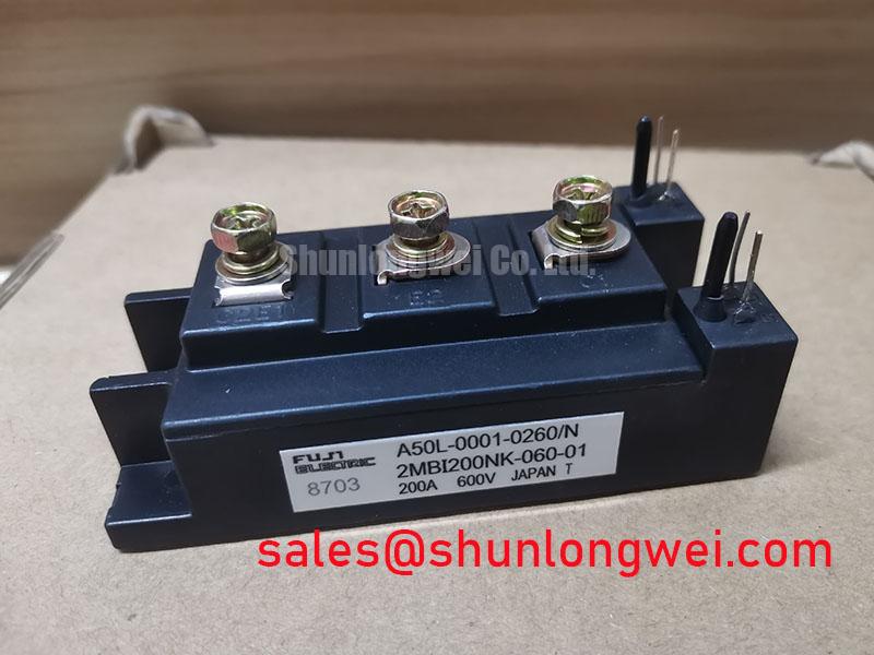
EVL31-055 is identified as a Fuji Electric power module in the 600.0 V, 100.0 A class, with a Fuji Power Module package description. Confirm these identification details and the applicable rating conditions against the manufacturer’s documentation before purchasing or installation. The device can be assessed for use in heavy-duty variable-frequency AC motor drive repairs, subject to the switching topology, cooling system, gate-driver design, and the original equipment documentation.
| Manufacturer | Fuji Electric |
| Model | EVL31-055 |
| Voltage class | 600.0 V |
| Current class | 100.0 A |
| Package description | Fuji Power Module |
During incoming inspection, use an ESD-controlled bench and allow the part to reach room temperature before comparing readings with a known-good reference. A multimeter diode function can help identify unexpected conduction between accessible power paths, but it is not a substitute for the manufacturer’s specified dynamic, thermal, or isolation tests. Gate terminals should remain electrically isolated from uncontrolled test sources, and the polarity marking must be matched against the drive board drawing rather than inferred from physical position alone.
💡 Bench Tip: Discharge the test fixture, short the meter leads to establish the lead-resistance reference, and record the cold-state readings before connecting any gate-drive harness.
Transient Dynamics and Electrical Design: Output Sinusoidal Filter versus dv/dt Reactor on EVL31-055
Long motor cables can transform a fast inverter edge into a reflected-wave event at the motor terminals, so the first engineering question is whether the installation requires a sinusoidal output filter or a dv/dt reactor. A sinusoidal filter changes the output waveform more extensively, while a dv/dt reactor primarily reduces edge steepness and limits the stress presented to the cable and motor insulation. The correct choice depends on carrier frequency, cable length, motor insulation capability, switching pattern, and the drive manufacturer’s output-filter requirements.
At the module level, switching overshoot is affected by commutation-loop inductance, busbar geometry, gate resistance, diode recovery behavior, and the DC-link layout. A long motor lead may produce terminal peaks approaching twice the local DC-link voltage in a severe impedance-mismatch condition; this is a system observation for oscilloscope investigation, not an EVL31-055 rating. Measure the phase-to-phase and phase-to-earth waveforms with a properly rated differential probe at the inverter output and at the motor end, using the same operating condition for both locations.
A practical filter decision starts with the motor manufacturer’s insulation limits and the drive supplier’s approved filter family. Do not select a reactor by the module’s 100.0 A label alone. The reactor’s current waveform, thermal rise, inductance tolerance, acoustic behavior, and bypass arrangement must match the complete drive. For a sinusoidal filter, verify capacitor current, resonance damping, low-frequency voltage drop, and regenerative operating behavior. Keep the switching loop compact, separate power and control wiring, and provide physical clearance that prevents a high-voltage output conductor from coupling into the isolated gate-control path.
The Fuji Electric V-Series IGBT Application Manual provides useful background for evaluating switching behavior, gate control, and protection coordination. In a field repair, compare the filtered and unfiltered waveform signatures rather than treating a replacement module as proof that the original transient problem has been removed.
EVL31-055 Operational Boundaries: Evaluating Optocoupler versus Digital Coreless Transformer Limits
The isolation component in the gate-driver board determines how reliably a switching command crosses from the control domain to the power domain during high common-mode voltage movement. Optocouplers and digital coreless transformer isolators have different propagation delay, pulse-width distortion, supply requirements, and common-mode transient immunity characteristics. The EVL31-055 identification does not establish the specification of the external isolator, so the driver board must be evaluated as a complete interface.
For a reinforced isolation design, verify the actual isolation rating, creepage path, clearance, insulation system, and transient test conditions of the selected driver. A barrier rated above 5 kV or an isolator with CMTI above 100 kV/µs must not be assumed from the module part number; any such system-level requirements must be confirmed from the driver datasheet and the equipment safety design. During commissioning, inspect the gate waveform at the module terminals with an isolated measurement arrangement, looking for unwanted narrow pulses, unequal turn-on timing, or excessive Miller-region disturbance.
The gate loop should have a short, controlled return path and a layout that keeps the high-current commutation loop away from the control reference. Gate-charge behavior, collector-emitter voltage slew rate, parasitic capacitance, and driver sink capability all influence the risk of spurious triggering. Active clamping or Miller-current control may be appropriate in some topologies, but the threshold and timing remain system design variables. The switching test should verify peak voltage and gate-emitter margins under the actual DC-link and load conditions.
When multiple modules are paralleled, static current sharing can benefit from a positive temperature coefficient of IGBT on-state voltage where the device characteristics show this behavior at the operating current and gate voltage, but this does not guarantee equal dynamic current sharing. Use symmetrical busbar paths, matched gate-drive propagation paths, and equivalent thermal conditions. Inspect the turn-on and turn-off current distribution with suitable current probes before approving the parallel arrangement. The Fuji Electric PIM power integrated module reference can help engineers compare package-level integration concepts, while the specific EVL31-055 gate interface must be matched to its original circuit.
Transient Dynamics and Electrical Design: Main Power Terminal Contact Resistance on EVL31-055
A bolted terminal joint can become the dominant local heat source when its contact condition deteriorates, especially in a drive carrying substantial continuous current. Inspect the mating surfaces for contamination, uneven seating, damaged threads, or evidence of previous thermal discoloration. A micro-ohmmeter with four-wire Kelvin measurement is more suitable than a standard handheld resistance range because the expected joint resistance is very small and lead resistance can obscure the result.
A contact-resistance value below 10 µΩ is sometimes used as a design or maintenance screening target for a high-current bolted joint, but it is not presented here as an official EVL31-055 terminal specification. The correct acceptance limit should come from the equipment manufacturer, the terminal hardware design, and the measured baseline of a properly assembled joint. Repeat the measurement after mechanical reassembly and compare each phase connection under the same probe pressure and contact position.
Thermographic inspection should be performed after the drive has reached a representative load condition. Compare equivalent terminals, phase symmetry, cable lug temperature, and the transition from lug to module terminal. A localized thermal pattern may involve joint pressure, conductor flexibility, busbar strain, or unequal current distribution; use the thermal image to direct a second inspection rather than assigning a single cause immediately. Check that the busbar does not pull laterally on the module terminal and that vibration from the cabinet or motor does not loosen the assembly over time.
Terminal work must also preserve electrical spacing. Keep conductive hardware, shield clamps, and cable screens from creating an unintended path between power terminals or toward the baseplate. The module’s identified 600.0 V electrical class does not establish the finished inverter’s insulation capability; coordinated insulation, creepage, clearance, enclosure, and pollution-environment evaluation are still required.
Field Diagnostics and Commissioning: Screening Substrate Ceramic DBC Micro-Crack in EVL31-055 Topologies
When a power module is installed on a conductive heatsink, insulation testing should be planned around the complete module-to-chassis assembly rather than only the semiconductor junctions. A high-voltage insulation tester can be used to evaluate terminal-to-baseplate isolation when the test voltage, duration, terminal connections, and acceptance criteria are defined by an authorized procedure. A value of at least 500 MΩ at 2.5 kV DC may appear in some system-level screening plans, but it is not identified here as an official EVL31-055 rating; apply only a test level authorized for the module and the connected assembly.
For topologies using a ceramic DBC substrate, a micro-crack can develop into intermittent isolation loss, localized heating, or a changing result after thermal cycling. Visual inspection should include the baseplate perimeter, mounting region, terminal area, and any location showing mechanical stress. These external checks cannot by themselves confirm or exclude an internal ceramic micro-crack. Do not use an insulation meter while the gate-driver board, snubber network, sensing circuit, or other low-voltage electronics remain connected. Remove contamination first, because airborne dust and moisture films can create a surface leakage path that does not represent an internal substrate defect.
Creepage and clearance should be checked from the actual conductive geometry, including busbar edges, screw heads, washers, cable lugs, and nearby grounded metalwork. Industrial dust can reduce the effective surface insulation path, so enclosure sealing, cleaning intervals, and airflow should be considered during commissioning. If the insulation result changes substantially with temperature or humidity, log the environmental condition and repeat the test after controlled cleaning and drying.
Thermal imaging, controlled insulation measurement, and comparison with an electrically equivalent phase can help separate a substrate-related concern from a terminal or wiring issue. Before testing, isolate the assembly from all power sources and verify that stored DC-link energy has been discharged. Stop the test if the reading becomes unstable or if the tester indicates discharge activity, and safely discharge the tested assembly afterward. For gate-loop layout, protection coordination, and practical switching considerations, the Precision Gate Drive Design guide provides a related engineering reference. For cross-reference evaluation, engineers may also examine the published 2MBI400TB-060-02 information, while treating compatibility as a circuit, mechanical, thermal, and control-interface decision rather than an automatic substitution.