


Content last revised on September 29, 2026
Benchtop Waveform Tuning: Current Sharing and Derating on F4-50R12KS4
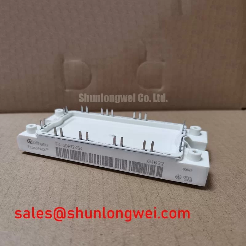
F4-50R12KS4 is an Infineon IGBT module. The supplied factory information does not establish a numerical voltage rating, numerical current rating, or a confirmed housing variant; the housing is described only as EconoPACK / PrimePACK. Read the markings and match the exact module documentation before using any of those values for a replacement decision.
Measure the cold resistance between each accessible gate and emitter terminal, then compare the readings with the removed unit and the drive schematic. With the DC link discharged and the module isolated as required by the service procedure, check the main power terminals for an unintended short. A multimeter can flag a gross fault, but it cannot establish switching performance or prove that the module is fit for service.
For a drive that uses parallel switching paths, inspect gate wiring symmetry and compare turn-on and turn-off waveforms under controlled test conditions. Unequal loop impedance can produce dynamic current imbalance even when static measurements look similar. A positive temperature coefficient of on-state voltage can assist steady-state sharing in an applicable device and operating region; it does not replace waveform measurement or confirm that this particular configuration supports parallel operation. This is a Design Consideration, not an F4-50R12KS4 factory rating.
Check measured collector-emitter peaks against the confirmed device rating and the drive’s DC-link behavior during switching tests. Keep high-current loops compact to limit inductive overshoot, while determining conductor spacing from the equipment’s insulation design, contamination conditions and applicable installation rules. For comparison work, FF600R12ME4P_B11 is a separate Infineon module reference, not an assumed drop-in substitute. Its topology, terminals, ratings and mounting interface need individual comparison.
F4-50R12KS4 Operational Boundaries: Investigating Gate Voltage Spikes
Probe the gate-to-emitter voltage at the module terminals during the complementary switch’s transitions. An off-state gate spike may reflect capacitive coupling from a fast collector voltage change; compare it with the driver output and the known-good phase before assigning a cause. Inspect the return path, driver connections and any fitted Miller-clamp function. A low-impedance clamp or negative off-state bias can be evaluated as a Design Consideration to reduce unintended turn-on, but the appropriate implementation depends on the confirmed module and driver limits.
Trace every terminal against the original equipment drawing rather than treating a similar-looking housing as a pinout match. Inspect creepage paths for contamination, confirm that nearby metalwork preserves the equipment’s required electrical clearance, and check busbar fasteners for movement or heat discoloration. If an optocoupler or digital isolator sits on the drive board, compare its common-mode transient behavior with the observed switching waveform; isolator behavior and gate-loop impedance can both affect what reaches the module gate. Infineon’s gate driver IC portfolio illustrates available driver functions, not a driver specification for this module.
Where the circuit also contains FF300R12KE3G, identify its actual position from the schematic before comparing drive supplies or protection timing. A shared equipment cabinet does not establish a shared gate-drive requirement.
F4-50R12KS4 Thermal and Electrical Integration: Mounting Surface Checks
Inspect the heatsink contact area for raised edges, trapped debris and uneven paste transfer when removing the failed assembly. Check the mounting face against the equipment’s flatness requirements; a fresh thermal interface cannot reliably compensate for an unsuitable mechanical fit. Apply the specified thermal interface material evenly, avoid visible voids and tighten fasteners in the sequence required by the housing and heatsink instructions. Paste thickness and torque are system and hardware decisions here, not verified F4-50R12KS4 specifications.
Field alert: Do not reuse a mounting torque or paste thickness from a different housing without checking the exact fastener and assembly instructions.
During a controlled restart, compare temperature readings at equivalent operating points and inspect terminal connections if one phase runs unexpectedly hot. Heating may reflect mounting contact, conductor resistance, switching behavior or the load; investigate those paths rather than attributing it to the module alone. Coordinate semiconductor fuse selection with the equipment designer using the confirmed device limits, prospective fault current and fuse clearing characteristics, including the fuse’s current-squared-time behavior. A fuse rating by itself cannot establish protection against a hard short circuit.
F4-50R12KS4 in Drive Deceleration: Checking Braking-Circuit Stress
Record DC-link voltage through a controlled deceleration and compare it with the drive’s braking-command signal and the confirmed module voltage limit. A rising link voltage calls for checks across the motor operating state, braking control, switching path and resistor circuit; it does not by itself identify a failed IGBT. Trace the schematic to determine whether braking uses a separate switch or a path within an installed assembly. The supplied F4-50R12KS4 information does not confirm an internal braking IGBT.
For a heavy-duty variable frequency AC motor drive evaluation, the equipment designer should assess braking-switch and resistor capability against the actual deceleration duty, then verify voltage and temperature margins by test. Thermal cycling at the module mounting interface also deserves inspection when repeated braking raises cabinet temperatures. The IGBT Design & Integration reference provides broader context for gate-drive and thermal checks; it does not supply missing ratings for this part. Infineon’s CIPOS Mini IPM series is a distinct integrated-module category, so its protection features must not be attributed to F4-50R12KS4.