



Content last revised on September 29, 2026
FF100R12MT4 Assembly Integrity and Layout Architecture
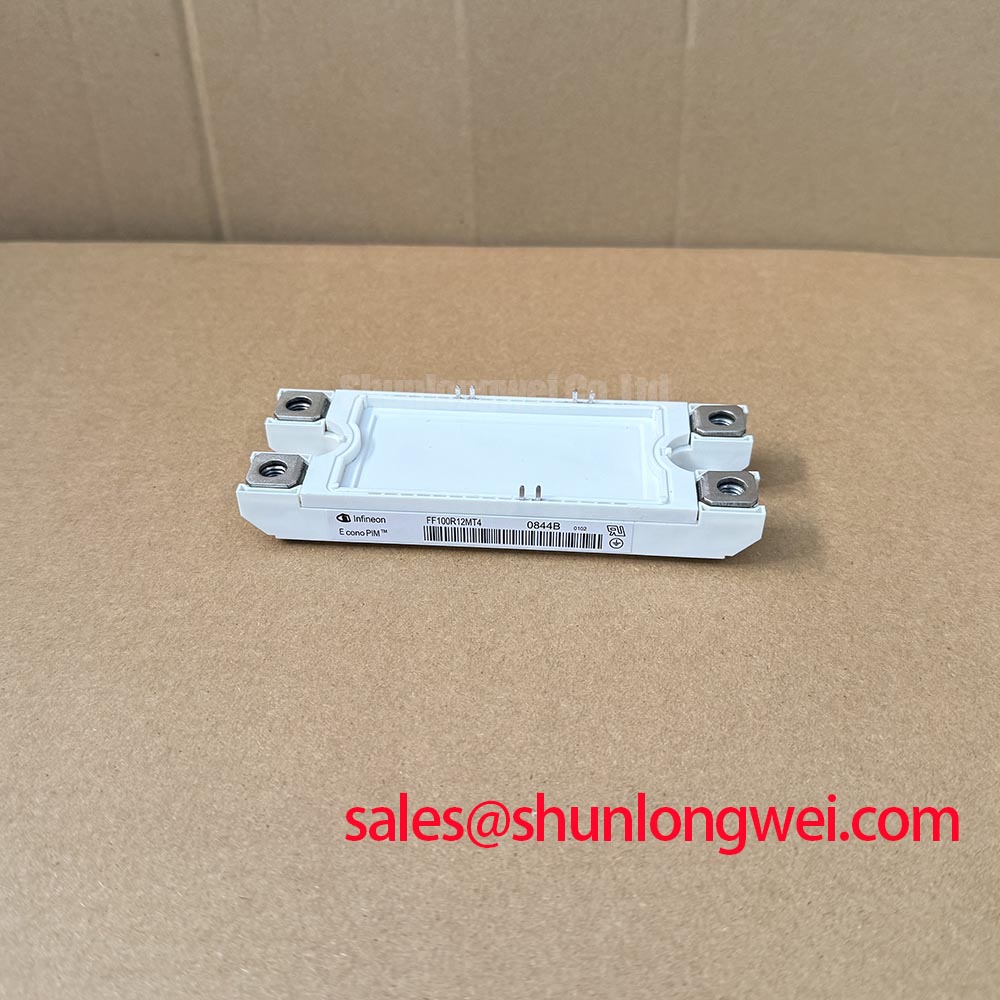
| Model | FF100R12MT4 |
|---|---|
| Manufacturer | Infineon |
| Category | IGBT Module |
| Topology | Dual Half-Bridge IGBT |
| Collector-emitter voltage rating | 1200 V (Official Specification) |
| Collector current rating | 100 A (Official Specification) |
| Package | Power Module |
| Series | Standard |
Probe the inverter output and the far end of a long motor cable when a drive reports overvoltage during switching. Different waveforms at those points can indicate reflected voltage caused by a mismatch between cable and load impedance; the module terminal waveform must be checked separately. Cable length, edge rate and termination affect the result, so an output filter should be selected from measurements made on the installed system, not from the FF100R12MT4 current rating alone. A common-mode choke addresses common-mode noise and should be evaluated separately. This is a Design Consideration, not an output-filter specification for the module.
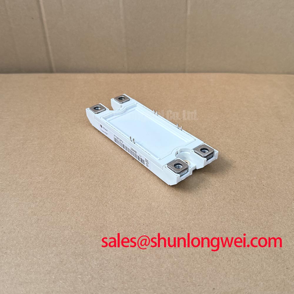
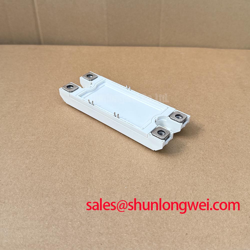
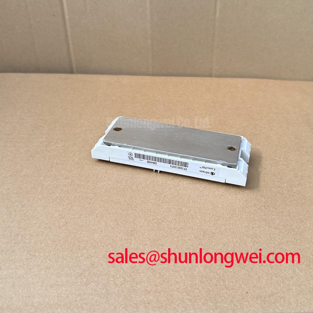
Inspect the module’s seating surface, terminal connections and the routing of the power and gate circuits. A connection that loosens under thermal cycling can change local heating and switching behavior without producing an obvious cold-test failure. Keep the outgoing and return power paths close where the assembly permits, and route gate connections away from high-current conductors. Creepage, clearance and enclosure spacing must be evaluated against the equipment’s insulation design; the 1200 V collector-emitter rating does not establish those distances.
For a repair, compare the original assembly drawing and circuit schematic with the dual half-bridge connections before moving conductors. The 100 A rating is an Official Specification, but usable current in an industrial inverter welder or medium-frequency induction heating supply depends on cooling, switching conditions and the complete thermal path. Inspect the heatsink contact and record the operating waveform after assembly rather than treating a successful continuity check as proof of fit. Infineon’s IGBT modules and discretes portfolio provides broader device-family context; it does not replace the equipment-specific connection drawing.
FF100R12MT4 Transient Dynamics and Isolation Interfaces
Capture the gate-to-emitter waveform during a switching transition if an otherwise intact phase leg triggers unexpectedly. A disturbance coinciding with a rapid switch-node transition may point toward common-mode coupling through the driver supply, isolation interface or gate loop. Inspect those paths individually before attributing the event to the module. The driver’s isolation-barrier rating and common-mode transient immunity are properties of the selected driver assembly, not stated specifications of FF100R12MT4.
As a Design Consideration, place the driver’s return path and gate loop so that power-current transients have fewer opportunities to disturb the commanded gate voltage. Evaluate Miller-induced turn-on with the actual driver, wiring and switching waveform. Negative off-bias or an active Miller clamp may be assessed as circuit-level measures, but the required method and settings are determined by the driver design and verified on the equipment. For the underlying gate-drive behavior, see Evolution of Negative Off-Bias Gate Drive Circuits.
Check the protection schematic alongside the isolation design. A semiconductor fuse must be coordinated with the complete fault path and the applicable device limits; its clearing behavior cannot be inferred from the module’s 100 A collector current rating. Likewise, any claim of reinforced insulation for the assembled drive requires evidence for the specified barrier and its installation. When reviewing a front-end or auxiliary power stage, FZ1800R12KF4_S1 can be examined as a separate component reference, subject to its own topology and ratings rather than assumed compatibility with this module.
FF100R12MT4 Fault-Clearing and Desaturation Behavior
Record the gate command, collector-emitter voltage and fault output together when a drive shuts down under load. Their order reveals whether desaturation detection followed an abnormal switching event or whether a control-path disturbance initiated the shutdown. Type-I and Type-II fault tests impose different initial conditions, so protection timing should be assessed against the selected driver and the module’s applicable safe-operating limits. No short-circuit withstand time is established by the specifications presented here.
Examine the driver schematic for desaturation blanking, fault latching and turn-off behavior, then verify those functions on the assembled drive using an appropriate controlled test procedure. A turn-off that is too abrupt for the installed power loop can increase inductive overshoot; a slower response changes fault energy. This trade-off is an Engineering Recommendation for system validation, not a prescribed delay or gate-resistor value for FF100R12MT4. Keep the voltage probe’s measurement loop short enough to distinguish a real terminal excursion from pickup in the test leads.
During component comparison, retain the distinction between matching headline ratings and matching an assembly. FS200R12PE4 is a separate model for cross-reference evaluation, not an identified drop-in replacement. Compare circuit topology, terminals, mounting interface, gate-drive requirements, thermal behavior and protection limits before considering any change. Infineon’s IGBT discretes and co-pack diodes information is useful background on device categories, but discrete-device characteristics should not be transferred to this power module without supporting specifications.
FF100R12MT4 DC-Bus Protection and Reliability Checks
Measure collector-emitter voltage at the module terminals during turn-off if the DC bus appears stable but overvoltage faults persist. The terminal peak includes the DC-link voltage and an inductive contribution that rises with stray loop inductance and current change rate. Minimize the outgoing and return loop area, then verify the measured peak under the equipment’s operating conditions against the relevant device limits. Snubber selection and busbar geometry are system decisions; the stated 1200 V rating is not a snubber-sizing rule.
Inspect busbar symmetry, capacitor connections and conductor joints before changing protection components. Unequal current paths can make apparently similar switching positions behave differently, while a poor joint can add both resistance and inductance. Pro Tip: Keep paired DC-bus paths geometrically consistent, then confirm turn-off voltage margin with measured switching waveforms rather than relying on the layout drawing alone. If waveform differences remain, compare positions with the same probe arrangement and operating condition.
Thermal checks should follow the same measured-load approach. Record case or heatsink temperatures at representative duty conditions and assess pulse heating with the module’s applicable transient thermal impedance data before estimating peak junction temperature. Freewheel-diode reverse recovery can also affect overshoot and radiated noise, but its softness must be evaluated from relevant device data and measured commutation behavior, not assumed from the dual half-bridge label. For equipment used at altitude, insulation coordination and environmental reliability remain system-level assessments; neither an altitude derating nor a field failure rate follows from the electrical ratings on this page.