

Content last revised on September 27, 2026
Benchtop Waveform Tuning and Voltage Stress on FS200R12PE4
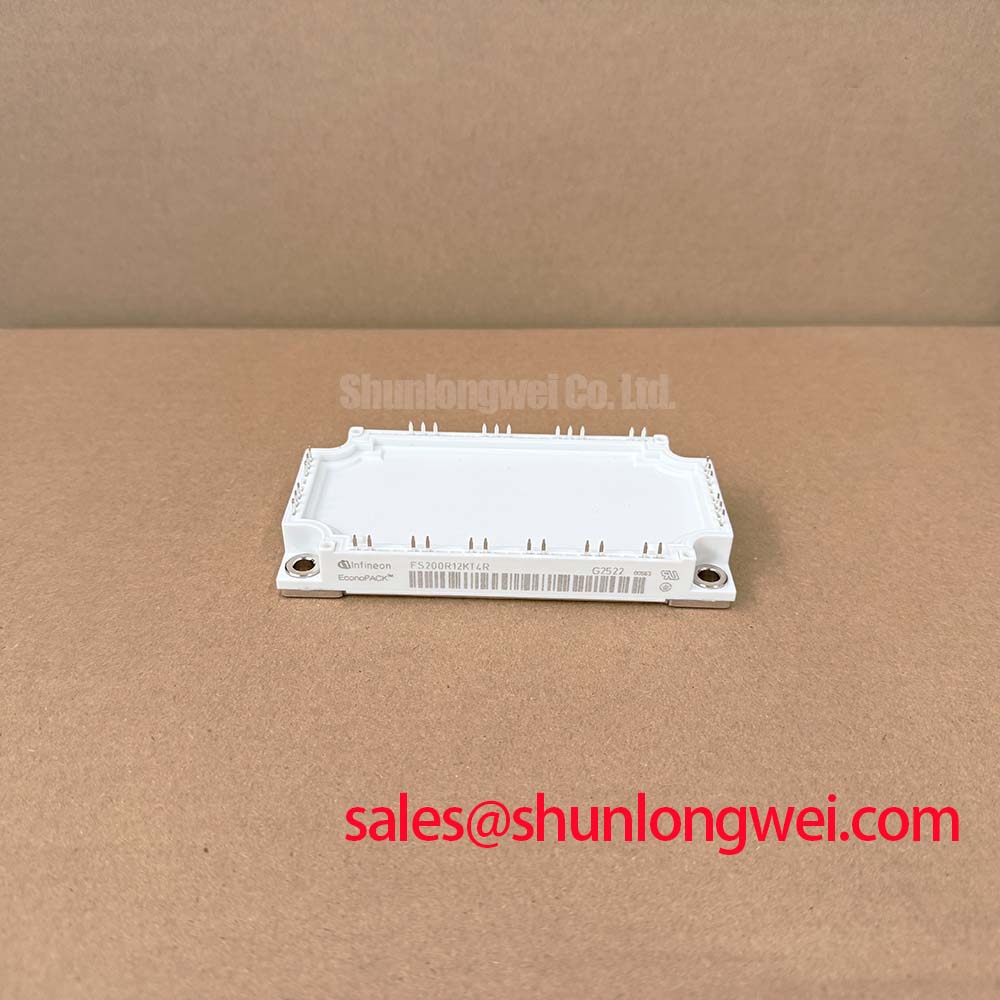
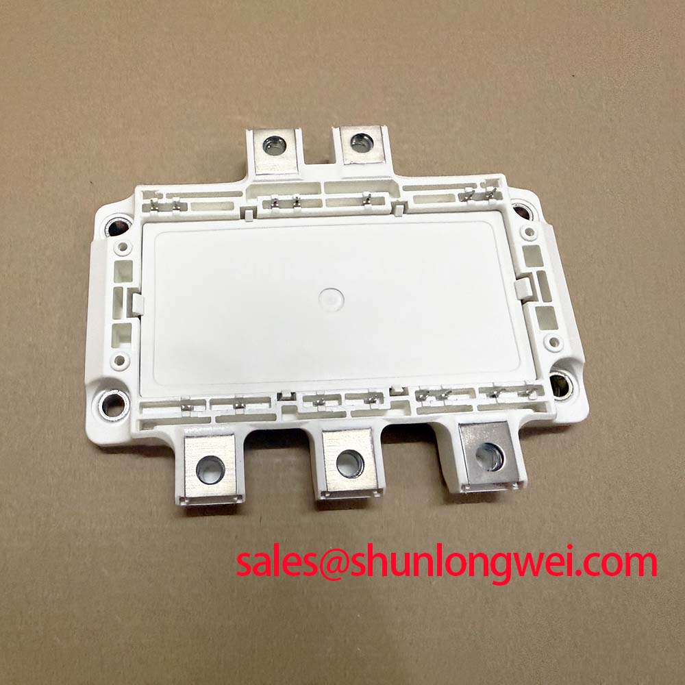
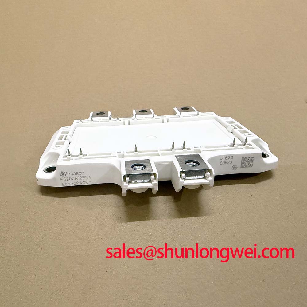
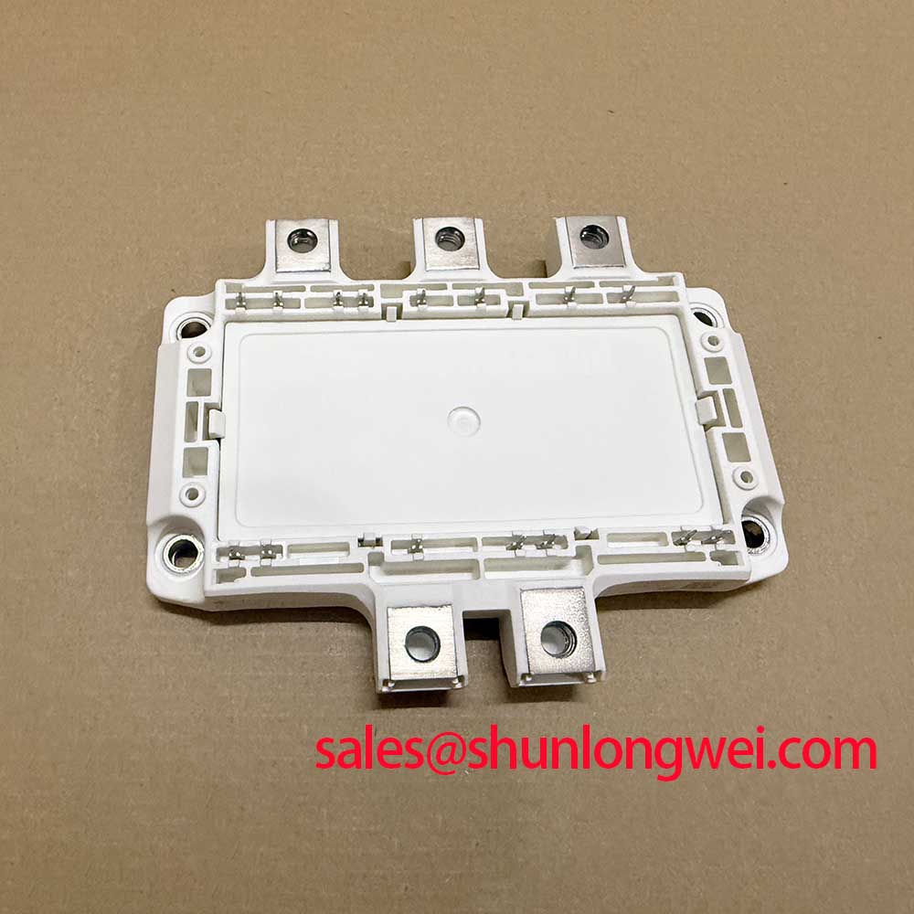
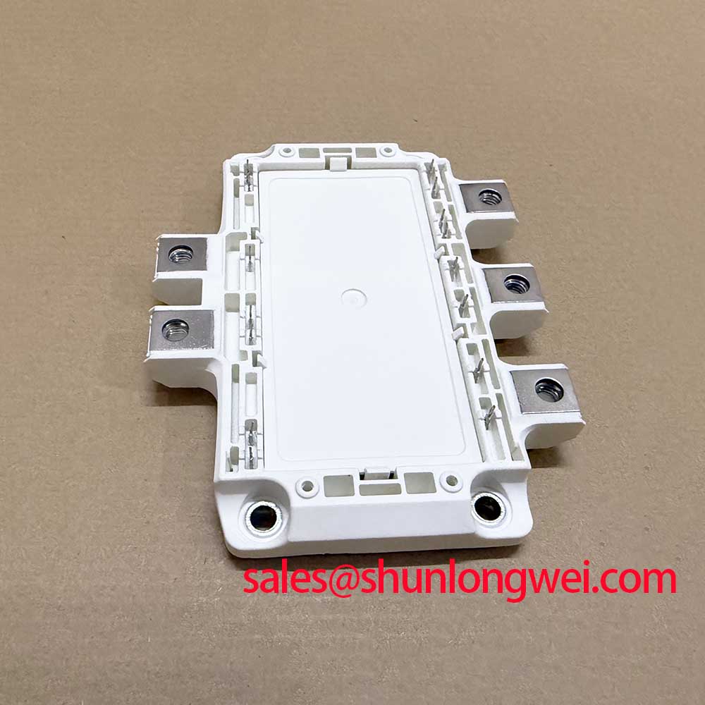
The Infineon FS200R12PE4 is an IGBT module with a collector-emitter voltage rating of 1200 V and a nominal collector current of 200 A (Official Specifications). Those ratings are the starting boundaries for evaluating the module in an existing drive, not permission to operate at either limit without checking the complete circuit. During replacement, compare the original module documentation, terminal arrangement, gate-driver connections, mounting interface, and protection scheme before applying power.
On the bench, look at the DC-link waveform and the collector-emitter voltage during turn-off under controlled operating conditions. The measured peak includes the bus voltage and an inductive overshoot from the commutation path. A laminated busbar and a compact capacitor-to-module connection can reduce loop parasitic inductance (Design Consideration), but the layout change is useful only if switching measurements confirm that the resulting peak remains within the module’s voltage boundary. Check both the waveform at the module terminals and the drive’s response to a protection event; a quiet steady-state bus reading can miss the stress that occurs during turn-off.
Where the original drive uses a metal-oxide varistor or another overvoltage absorber, treat it as part of the system-level protection network rather than as a substitute for controlling switching overshoot (Design Consideration). Compare its installed connections and service condition with the original circuit drawing. An absorber that acts on a slower bus surge does not necessarily clamp a fast voltage excursion at the IGBT terminals. If a waveform shows excessive ringing, examine the capacitor path, busbar joints, gate-drive return path, and measurement probe arrangement before assigning the cause to the module.
Altitude and radiation-related failure mechanisms cannot be converted into a credible failures-in-time figure for this installation from the module ratings alone. Neutron exposure, operating voltage, location, and device-specific reliability evidence would all matter to such an assessment. For equipment operating at altitude, designers should review the complete drive’s cooling and voltage margins as a Design Consideration; no altitude derating curve or single-event-burnout rate is claimed here for FS200R12PE4. Infineon’s automotive-qualified power module information concerns a distinct qualification context and should not be read as an automotive qualification claim for this module.
Transient Switching Loss and Thermal Checks for FS200R12PE4
For FS200R12PE4, the typical turn-on energy is 28.00 mJ and the typical turn-off energy is 22.00 mJ, both specified at 125 °C (Official Specifications). The specified junction-to-case thermal resistance is 0.27 K/W per switch, and the operating junction-temperature range is −40 to 150 °C (Official Specifications). Keep the test conditions attached to the energy figures when comparing them with measured drive behavior: actual switching loss depends on the operating current, bus voltage, gate circuit, and switching conditions.
During a controlled restart, inspect the gate and collector-emitter waveforms together. Slowing a transition may reduce voltage overshoot while increasing switching energy; speeding it up may have the opposite effect (Design Consideration). There is no gate-resistance setting that can be selected from the headline energy figures alone. The system engineer should verify switching behavior, protection timing, and temperature under the drive’s actual load cycle rather than copying a setting from another inverter.
The 0.27 K/W junction-to-case value describes a specified thermal path per switch; by itself it does not predict the junction-temperature peak during a short overload. That estimate also needs the module’s applicable transient thermal impedance data, the case temperature at the start of the event, and the pulse history. Without those inputs, a multi-RC model would give a deceptively precise answer. For field evaluation, inspect the heatsink contact, cooling path, fan operation if fitted, and case-temperature trend while reproducing the fault within a controlled test plan.
Field alert: Discharge the DC link before disturbing module terminals, and follow the documented fastener and mounting-surface requirements rather than tightening by feel.
Electric forklift traction drives are one possible compatibility assessment, but the nameplate power of a truck does not establish module suitability. Compare the actual DC-link voltage, motor-current cycle, enclosure cooling, and mechanical fit with the original drive design. If an overload occurs during acceleration or a repeated stop-start duty cycle, capture current and temperature behavior before attributing the trip solely to insufficient module current rating.
Regenerative DC-Bus Surges and Protection Coordination
A drive that trips during deceleration deserves a DC-link measurement before a power module is changed. Regenerative energy can raise bus voltage when the motor returns energy faster than the system can accept it. Check the drive fault record, bus-voltage waveform, and braking-circuit operation against the original schematic. A rising bus during braking may point toward a protection or energy-handling issue, but it is not, on its own, proof of a failed braking transistor or resistor.
The supplied FS200R12PE4 specifications do not identify an internal braking IGBT or provide a braking-resistor rating. Do not infer either from the traction application. Where the equipment has an external braking path, its transistor, resistor, wiring, control threshold, and thermal limits must be evaluated from the drive documentation (Design Consideration). Resistor selection depends on the energy returned during the actual deceleration profile and on how frequently that event repeats; it cannot be prescribed from the 1200 V module rating.
Separate a regenerative bus rise from a switching transient when diagnosing overvoltage. Capture the DC link over the braking event, then inspect the faster collector-emitter waveform during switching with an appropriate measurement setup. If the bus rises gradually, investigate the intended energy destination and braking controls. If the module-terminal voltage spikes during turn-off, inspect the local commutation loop and its connections. The two effects can occur in the same drive and may call for different corrective work.
For a replacement review, FS200R06KL4 can be examined as a separate Infineon module option, but it should not be treated as a verified direct substitute for FS200R12PE4. Confirm its own voltage rating, electrical behavior, terminal layout, mounting dimensions, and driver requirements against the original equipment documentation before considering a design change. A matching current figure or a familiar model prefix is not enough to establish interchangeability.
Current Sharing, Gate Paths, and Return-to-Service Checks
Where a drive connects switching devices in parallel, distinguish steady-state current sharing from switching-time current sharing. A positive temperature coefficient of on-state voltage, when demonstrated under the relevant operating conditions, can assist static sharing; it does not guarantee equal transient currents (Design Consideration). The supplied FS200R12PE4 data does not establish a universal positive coefficient across the drive’s current and temperature range. Compare the applicable on-state characteristics and the complete parallel circuit before relying on thermal self-balancing.
For dynamic balance, inspect whether parallel gate paths have comparable routing and whether their power connections produce similar commutation loops. Unequal path impedance can change turn-on or turn-off timing even when the driver issues the same command (Design Consideration). During a controlled test, compare individual branch-current and gate-waveform measurements where the equipment provides safe access. Correct the identified wiring or drive discrepancy according to the original design, then recheck voltage overshoot and protection response under load.
A cold meter check remains useful at the end of the repair: compare each accessible switch path with the equipment schematic and note any unexpected low-resistance path before energizing. Follow that with staged electrical testing and a review of the original fault record. A normal static reading cannot clear a module of dynamic faults, just as a protection trip cannot identify a single failed part without measurements. The Power Electronics Masterclass provides broader context for checking voltage stress, switching behavior, and system-level reliability during that review.
Finally, keep module function distinct from a complete power stage. Infineon’s intelligent power module overview describes products with integrated functions; it does not establish that FS200R12PE4 contains the same drive or protection circuitry. Before returning the equipment to service, verify the actual gate driver, fault reporting, cooling, and overcurrent response in the installed system.