

Content last revised on October 15, 2026
FP100R12KT4G Thermal-Electrical Optimization: Bi-Directional DC-DC Buck-Boost Conversion Practical Tuning
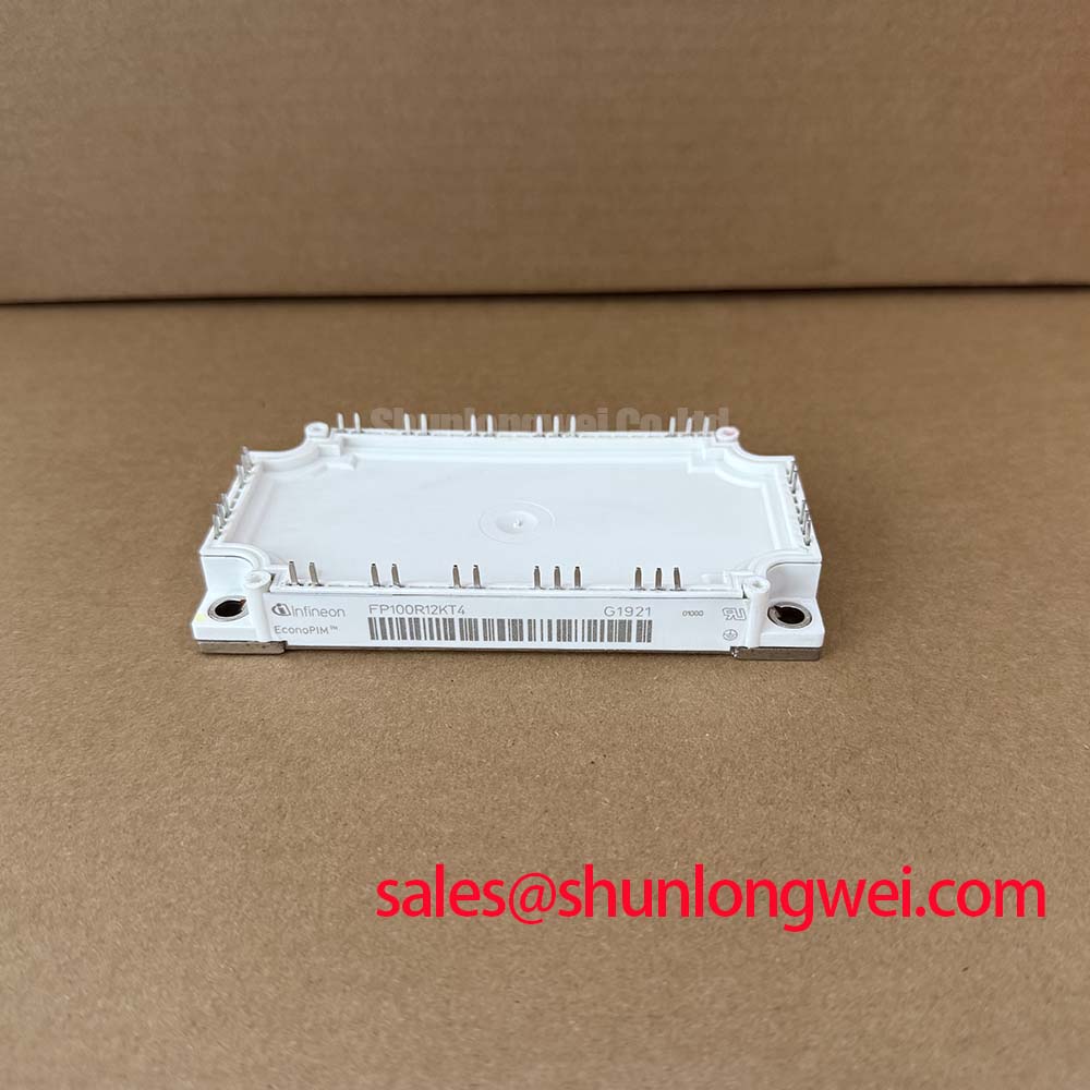
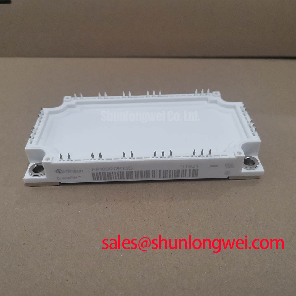
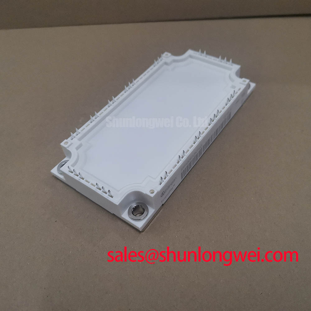
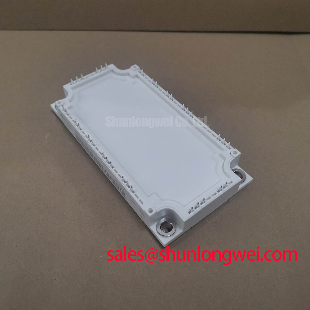
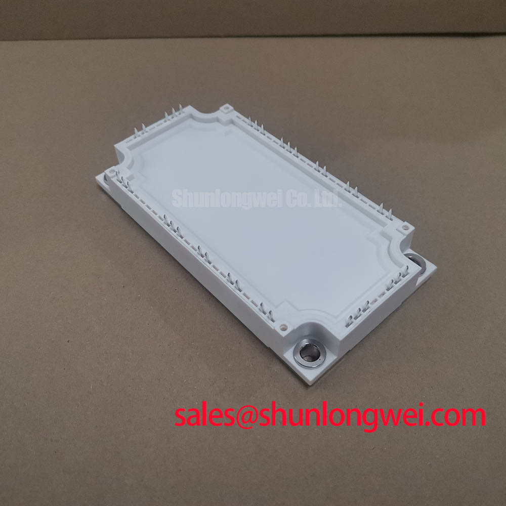
Isolate the DC supply, verify discharge of the DC link, and compare the installed module marking with the equipment parts record before disconnecting its power terminals. For an Infineon FP100R12KT4G, the core electrical identification is 1200 V blocking voltage and 100 A rated current under the specified datasheet conditions. Commissioning decisions also require the applicable circuit connections, cooling conditions, and switching limits.
Keep the removed assembly’s terminal map, driver connections, mounting hardware, and thermal interface record together. This gives maintenance and procurement personnel a common reference when evaluating the replacement. Commercial string inverters and micro-grid energy storage converters are potential compatibility assessment contexts, subject to the equipment schematic and qualification requirements; the module ratings alone do not establish suitability for a particular converter.
Compare current direction, DC-link voltage, switching commands, and temperature trends across charging and discharging transitions before changing the control settings. As a Design Consideration, bidirectional buck-boost operation depends on the complete converter circuit and control strategy. Four-quadrant operation requires the surrounding system to support the intended voltage polarities and current directions; it cannot be inferred from the FP100R12KT4G voltage and current ratings.
Trace the battery connection, inductive energy storage path, switched nodes, and DC-link return on the equipment schematic. Identify which semiconductor positions conduct during each operating state, including freewheeling and transitions between power directions. This separates an unexpected current path from a control timing problem. Where a measured waveform differs between charging and discharging, compare the corresponding driver supplies, current sensor polarity, and switching commands under equivalent operating conditions.
For thermal tuning, an Engineering Recommendation is to correlate case temperature and heatsink temperature with load history rather than judging the assembly from a single steady reading. Repeated peak shaving can produce temperature excursions even when the average current appears moderate. Record the temperature response during load application, load removal, and reversal, using repeatable measurement positions. Case measurements support troubleshooting, but they do not directly establish semiconductor junction temperature.
Temperature drift that develops through successive cycles warrants inspection of airflow, coolant performance where applicable, interface condition, and switching behavior. Keep these observations separate in the maintenance record. A rising heatsink temperature suggests a different investigation from a growing temperature difference between the module and its mounting surface. Neither observation identifies a unique fault without comparison against the operating load and the established equipment baseline.
As a Design Consideration, keep the commutation path compact to limit inductive overshoot, while preserving the required separation between power conductors, control connections, and accessible metalwork. Determine creepage and clearance from working voltage, insulation function, pollution conditions, material classification, and the applicable equipment standard. Inspect the assembled busbars and cable lugs because their edges, fastening hardware, and routing can change the separation available around the module terminals.
During regenerative events, trace where returned energy actually goes. Battery acceptance limits or a disconnected energy sink can cause the DC-link voltage to rise despite correctly commanded switches. If the equipment includes a braking chopper and resistor, assess their operation against the equipment’s energy balance and protection sequence. Resistor pulse capability, average dissipation, and thermal protection belong to that assembly’s qualification; the module’s 1200 V rating does not establish an energy absorption capability.
Rectification, bidirectional conversion, and braking should remain distinct functions in the circuit review. The FP150R12KT4 is a related product for a separate topology and rating assessment when reviewing associated power conversion stages. Its inclusion in a procurement comparison should follow examination of its circuit diagram, terminal arrangement, and cooling requirements rather than an assumption that it serves as a complementary stage in every installation.
FP100R12KT4G Operational Boundaries: Evaluating Heatsink Contact Pressure
Inspect the heatsink contact surface for contamination, raised burrs, corrosion, and witness marks before fitting the FP100R12KT4G. As a Design Consideration, thermal interface material should fill surface irregularities without creating an unnecessarily thick thermal barrier. Select the application method and bond line from the approved module mounting procedure and the interface material instructions, then check the resulting coverage during assembly qualification.
A prescribed grease thickness is inappropriate without the corresponding mounting specification. Stenciling, dispensing, and pre-applied materials produce different contact patterns under pressure. Evaluate coverage across the intended mounting footprint, with attention to voids and displaced material. Do not use additional compound to compensate for a damaged mounting face or an unqualified heatsink geometry; those conditions require mechanical assessment before the assembly returns to service.
Baseplate curvature and clamping behavior should be assessed against the applicable mechanical drawing and mounting instructions. As an Engineering Recommendation, follow the specified screw sequence and torque with calibrated tools so contact pressure develops consistently. Distinguish the fasteners securing the module to the heatsink from those securing electrical terminals. Their loads, thread engagement, and tightening requirements serve different functions and should have separate entries in the assembly record.
Support busbars so their weight, thermal movement, and vibration do not impose uncontrolled loads on the terminals. Check alignment before tightening rather than drawing misaligned conductors into position with the fasteners. Where the equipment uses locking hardware, retain the approved arrangement and inspect its condition during planned service. Any change in washers, spacers, conductor thickness, or lug orientation should trigger a review of both mechanical loading and electrical spacing.
Pinout verification belongs at the interface between procurement and installation. Match every power and control connection to the circuit diagram, including any auxiliary connections actually documented for the device. For replacement planning, compare the FS100R12KT4G_B11 through its own schematic, footprint, terminal positions, and driver requirements. Similar naming or matching headline ratings does not establish interchangeability; substitution requires equipment-level approval.
Inspect creepage paths after cleaning and reassembly, especially where residue, conductive dust, or displaced interface material could affect the surrounding insulation surfaces. As a Design Consideration, condensation control depends on cabinet conditions, storage history, and temperature transitions. Check for moisture before energization after a cold shutdown or relocation, and address the enclosure conditions responsible for recurrence. Cleaning methods should remain compatible with the module housing and adjacent insulation materials.
Maintenance Note: Trend terminal temperature under comparable loads and check airflow during scheduled service so changes in connection condition or cooling performance receive attention before the next operating cycle.
Set inspection intervals from the equipment duty, contamination exposure, and recorded thermal behavior. Review thermal interface condition when the module is removed or when temperature trends justify investigation, rather than assuming a universal replacement interval. The IGBT Design & Integration reference provides broader context for coordinating cooling, gate drive, and circuit topology when maintenance findings lead to an engineering review.
Transient Dynamics & Electrical Design: Negative Gate Bias vs Active Miller Clamping on FP100R12KT4G
Measure the gate-to-emitter waveform at the module connection during complementary switching to investigate unintended turn-on. As a Design Consideration, collector voltage transitions can couple displacement current into the gate circuit through device capacitance. The resulting gate disturbance depends on the driver’s sink path, connection inductance, and switching conditions, so the measurement must represent the local gate reference rather than a distant control ground.
Negative gate bias and an active Miller clamp address this disturbance through different circuit actions. Negative bias increases the separation between the off-state gate potential and turn-on conditions. A Miller clamp provides a low impedance discharge path when its operating conditions are satisfied. Assess either approach against the module’s gate limits, the driver architecture, and measured transients; select the bias and clamp behavior through the equipment design process.
Keep the gate discharge loop short and separate it from high current commutation paths. An Engineering Recommendation is to examine the complete return route, including connectors and any shared conductor sections, before adjusting gate resistance. A resistor change can alter switching speed, overshoot, and losses together. Compare these effects under representative operating conditions instead of treating suppression of a single gate waveform peak as sufficient evidence of improvement.
Check the measurement arrangement when gate ringing or unexpected pulses appear. Probe loop pickup and common-mode disturbance can obscure the actual signal. Use appropriately rated differential measurement equipment and compare the driver output with the waveform at the module terminals. A difference between those locations can help direct attention toward interconnect behavior, while a disturbance already present at the driver requires examination of its supply, input, and reference paths.
For isolated driver boards, assess common-mode transient immunity against the measured switching environment and the isolator manufacturer’s conditions. As a Design Consideration, optocoupler or digital isolator performance must cover the relevant transient polarity, supply state, and output behavior. Inspect isolation barrier layout and supply decoupling alongside the signal path. A module voltage rating does not establish the immunity or insulation performance of its associated driver board.
Where parallel operation is under review, the Infineon IGBT Paralleling Application Note provides manufacturer guidance for evaluating current sharing and connection symmetry. Apply that assessment to the proposed assembly before accepting a parallel arrangement. The Infineon IGBT Modules Overview also provides manufacturer context for product family comparisons without establishing replacement compatibility.
For installations at elevated altitude, treat electrical spacing and cosmic ray susceptibility as separate engineering assessments. As a Design Consideration, obtain applicable insulation guidance and manufacturer reliability information before assigning an operating limit or failure rate. Close the driver investigation by recording the tested bus conditions, gate waveforms, protection response, and thermal state, giving the equipment engineer a reproducible basis for approving the repaired assembly.