


Content last revised on October 28, 2026
FF150R17KT4 Identification and Pre-Service Checks
- Isolate the equipment, verify that stored energy has discharged, and record cold-state measurements between the power terminals before disconnecting the existing wiring.
- Compare the module marking, terminal arrangement, and mounting interface with the equipment service drawing.
- Inspect the heatsink contact surface, thermal interface material, and terminal supports for contamination, displacement, or mechanical loading.
- Trace the gate-driver return separately from the load-current path and check for moisture around the control connections.
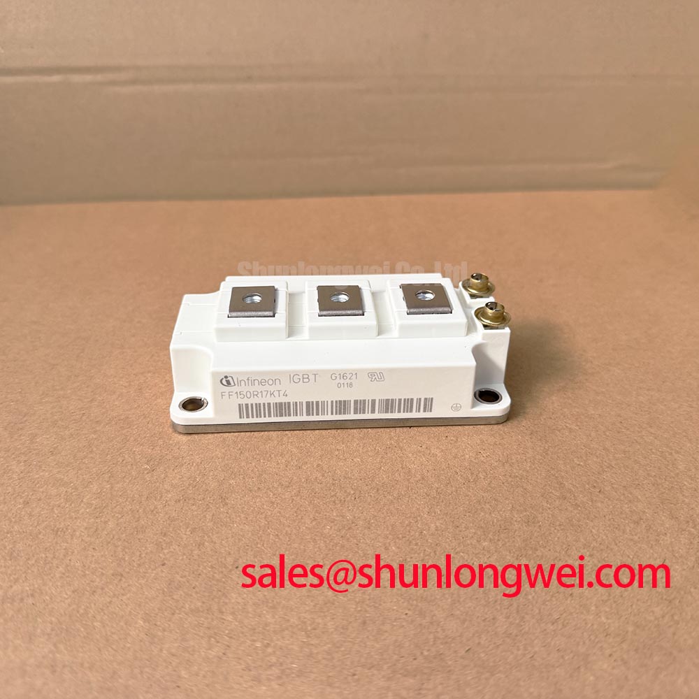
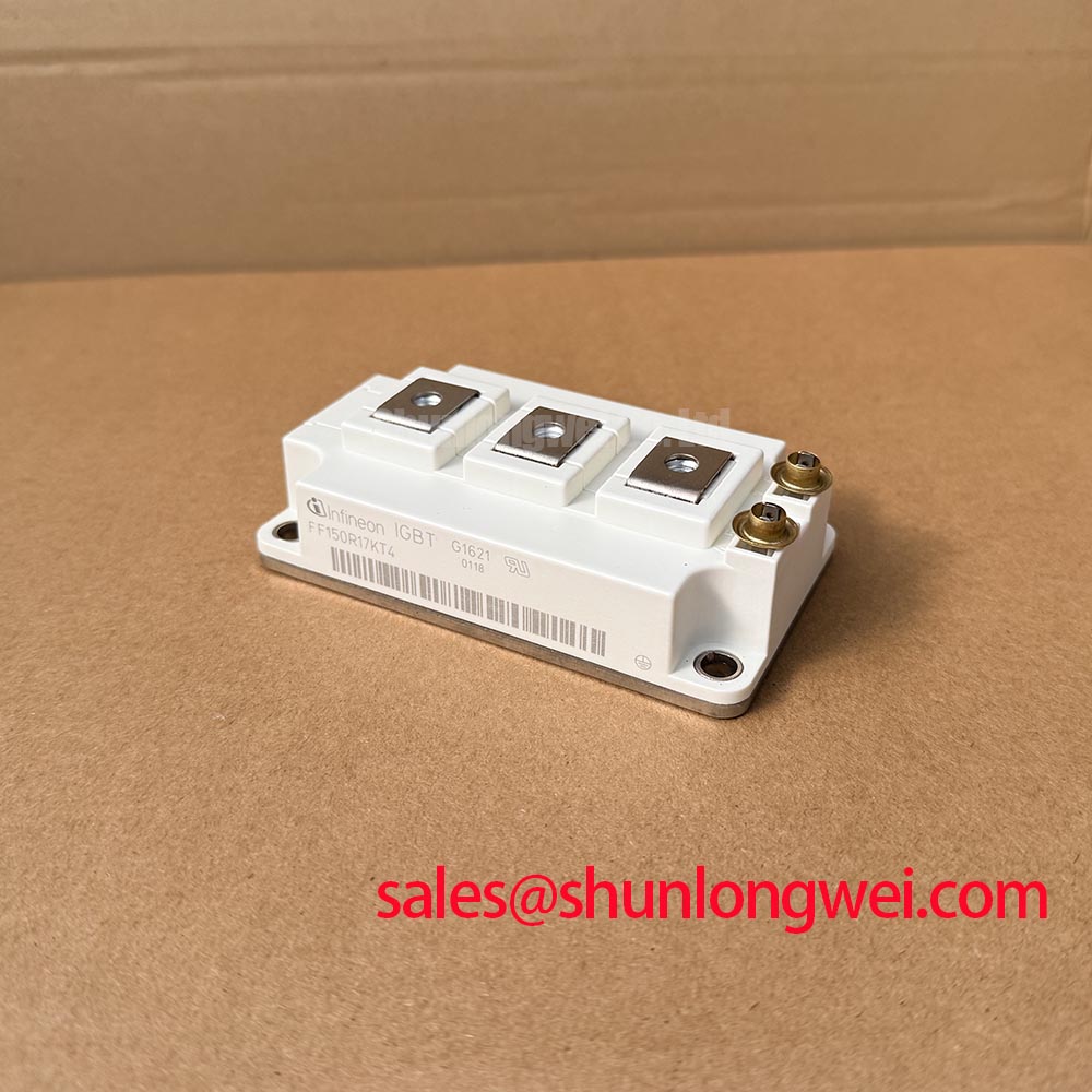
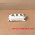
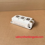
The FF150R17KT4 from Infineon is an IGBT module with a 1700 V voltage rating and 150 A rated collector current under the datasheet-specified conditions. For maintenance planning, these electrical identifiers establish the starting point; the equipment schematic and module interface drawing establish whether the part fits the existing power stage.
| Product characteristic | Specification | Parameter identity |
|---|---|---|
| Model | FF150R17KT4 | Manufacturer designation |
| Manufacturer | Infineon | Product identity |
| Rated voltage | 1700 V | Official Specification |
| Rated collector current | 150 A, under datasheet-specified conditions | Official Specification |
| Package category | Module | Official Specification |
| Detailed electrical and mechanical limits | Consult Datasheet | Terminal map, rating conditions, switching characteristics, thermal data, and assembly instructions |
The commissioning and maintenance practices below are Design Considerations, not additional manufacturer specifications. They address the external electrical connections, mechanical interfaces, and operating measurements that determine whether a replacement can return to service without carrying forward an unresolved equipment fault.
FF150R17KT4 Thermal-Electrical Optimization: Cosmic-Ray Robustness and Voltage Derating
Record the actual blocking-voltage exposure at the module terminals, including switching overshoot and abnormal operating events, before assessing voltage headroom. A DC-link display alone does not capture the peak voltage imposed on the semiconductor. Use appropriately rated measurement equipment and a probing arrangement that does not introduce a misleading ringing waveform.
Design Consideration: Cosmic-ray susceptibility belongs in the equipment reliability assessment when site elevation and sustained blocking voltage are relevant. Terrestrial neutron exposure can vary with installation conditions, but elevation by itself is not a model-specific failure-rate specification. A defensible single-event burnout assessment requires semiconductor-specific susceptibility data, the relevant radiation environment, and the operating voltage and temperature profile. A generic altitude multiplier cannot establish an FF150R17KT4 failure-in-time rate.
For practical voltage-headroom evaluation, review the highest sustained DC-link condition alongside measured switching peaks. Examine busbar connections, commutation paths, and suppression components when comparing waveforms with the equipment baseline. Any proposed voltage reduction should be evaluated against converter functionality and the manufacturer's applicable reliability guidance, rather than selected as an arbitrary percentage of the 1700 V rating.
Clearance assessment is a separate task from semiconductor blocking-voltage assessment. Designers should determine conductor spacing from the equipment insulation-coordination requirements, installation environment, and applicable standards. Inspect for conductive deposits, damaged barriers, and condensation tracks, particularly where temperature changes bring cabinet surfaces below the local dew point. Increasing semiconductor voltage headroom does not correct a compromised external insulation path.
For broader equipment context, the Industrial Applications resource can support system-level discussion, but it is not a source of model-specific lifetime or radiation guarantees. Infineon's reverse-conducting IGBT application note concerns a particular device architecture; its operating guidance should not be transferred automatically to this module.
FF150R17KT4 Thermal-Electrical Optimization: Auxiliary Emitter Pinout Cold-Check Practical Tuning
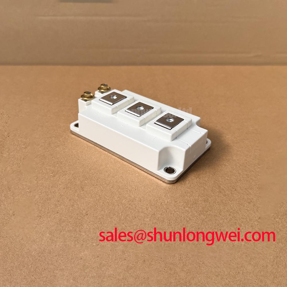
Identify the main emitter connection and the gate-driver reference from the module terminal drawing before making continuity checks. Where the documented terminal arrangement provides a separate auxiliary emitter connection, trace it to the driver return rather than treating it as an interchangeable load-current terminal. Physical proximity does not establish electrical function.
Design Consideration: A driver return sharing substantial load-current inductance can experience a voltage disturbance during current transitions. That disturbance changes the gate-to-emitter voltage seen by the semiconductor, even when the driver output appears stable at its own connector. Keep the outgoing gate path and its intended return closely associated, and assess their separation from the commutation loop using the actual assembly geometry.
Cold checks should establish connection integrity without assigning a universal pass voltage to a handheld meter reading. Parallel paths through drivers, protection networks, and other power devices can affect the result. Record measurement polarity and connection state, then compare corresponding paths under the same conditions. During controlled powered testing, evaluate gate-to-emitter voltage at the appropriate module connections and account for probe common-mode capability.
If the equipment parallels switching positions, current sharing requires attention to both electrical and thermal symmetry. A positive temperature coefficient of on-state voltage can assist static sharing in the operating region where the manufacturer's characteristic curves demonstrate it; it does not establish equal dynamic current. Designers should assess busbar impedance, driver timing, connection resistance, and cooling distribution together.
The F4-150R17ME4_B11 can be included in a documented hardware comparison, but it should not be described as a verified direct replacement without matching topology, terminal mapping, mounting geometry, driver requirements, and thermal performance. Matching headline voltage and current ratings is only part of that comparison.
For a utility-scale centralized battery energy storage PCS compatibility assessment, engineers should map every switching position and driver channel before selecting a service part. A separate module such as the FF1000R17IE4 is relevant only where the system schematic identifies a suitable power-stage role; it is not automatically a rectifier or a complementary drop-in stage. Likewise, thyristor gate-trigger current, gate-trigger voltage, and pulse-train triggering are not FF150R17KT4 IGBT control specifications.
FF150R17KT4 Thermal-Electrical Optimization: Preventing Mechanical Stress on Terminal Connections
Check terminal fastener engagement and busbar alignment before applying tightening torque. A fastener that bottoms out can produce a torque reading without establishing the intended clamping condition. A misaligned busbar can also place sustained bending load on the terminal after the tool has been removed.
Design Consideration: Support the external conductors so that their weight, vibration, and thermal movement are not reacted primarily through the module terminals. Bring mating surfaces together without using the terminal screws to pull a distorted busbar into position. Use the specified fastener and washer arrangement, checking engagement against the assembly drawing rather than assuming that a familiar screw diameter implies a familiar installation torque.
Assess potential connection damage through observable assembly conditions, not an assumed internal failure mechanism. Terminal discoloration, movement, or rising contact temperature can justify further investigation, but none independently establishes a cracked internal connection. Compare accessible joint resistance and thermal behavior with equivalent connections under comparable loading, and review the mechanical support before deciding on corrective work.
Torque-tool calibration belongs in the maintenance record, alongside the assembly procedure and any connection repairs. Repeated tightening without assessing the joint can obscure the original condition and may disturb a sound connection. Follow the equipment manufacturer's inspection method for checking existing joints; do not automatically apply installation torque as a periodic retightening instruction.
Maintenance Note: Trend terminal temperature and inspect airflow at planned service intervals rather than treating screw retightening as a substitute for diagnosing a hot connection.
When temperature rises coincide with changed switching behavior, separate connection heating from semiconductor loss. Diode reverse recovery can influence commutation current, voltage overshoot, and electromagnetic emissions, but a recovery-softness factor is meaningful only with its definition and test conditions. Do not assign an undocumented softness value to this part. Compare waveforms at equivalent current, temperature, and driver conditions before attributing a change to the module rather than the surrounding circuit.
Field Diagnostics & Commissioning: Baseplate Convexity Inspection in FF150R17KT4 Topologies
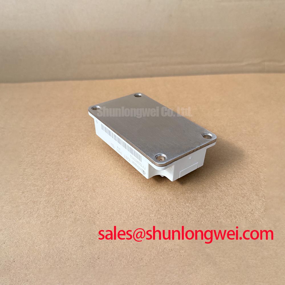
Inspect the module mounting surface and heatsink for burrs, embedded debris, corrosion, and uneven contact marks before applying fresh thermal interface material. Assess baseplate profile against the manufacturer's permitted geometry; an apparently convex surface is not, by itself, evidence of damage. Avoid machining or flattening the module to satisfy an improvised straightedge test.
Design Consideration: Thermal interface material should fill the intended contact irregularities without becoming an unnecessarily thick thermal barrier. Select its application method and final bond line from the approved module, heatsink, and material combination. A generic thickness target is not an FF150R17KT4 assembly specification, and paste extrusion around the perimeter does not prove uniform contact beneath the module.
Use the prescribed mounting sequence and calibrated tooling to develop contact pressure without imposing local bending. A staged diagonal sequence can be considered where the assembly instructions permit it, but the actual sequence, torque, and fastening conditions remain assembly-specific. Inspect the mating surfaces whenever the module is removed, and replace disturbed interface material according to the approved service procedure.
Evaluate thermal performance under a repeatable operating condition after installation. Compare coolant or inlet-air temperature, heatsink temperature, electrical loading, and switching conditions with the equipment baseline. Transient thermal impedance, Zth, relates time-varying dissipation to junction-temperature response; selecting the appropriate network requires the manufacturer's thermal model and a representative loss profile. Case temperature alone cannot establish the peak junction temperature during a pulse.
The discussion of packaging and thermal performance in Infineon TRENCHSTOP™ IGBT7 technology provides useful context for why construction matters, but it does not establish IGBT7 or SLC construction for the FF150R17KT4. Apply only the thermal and assembly data belonging to the installed part.
Set inspection frequency from cabinet contamination, operating duty, and observed temperature trends rather than an invented service-life interval. Clean heatsink passages using the equipment-approved method, check fan and filter condition, and examine accessible interface edges for displacement. After a cold shutdown or humid maintenance exposure, resolve condensation before energization. Retain the post-service temperature and waveform records so the next inspection can distinguish gradual cooling degradation from a change in load or switching behavior.