Content last revised on January 4, 2026
FF300R12KT3: Technical Review of a 1200V, 300A Dual IGBT Module
Engineered for High-Frequency Switching and Thermal Stability
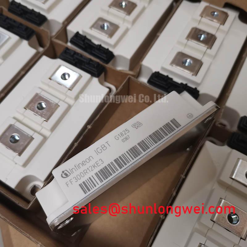
The FF300R12KT3 is a 1200V, 300A dual IGBT module engineered for demanding power conversion systems. Leveraging Infineon's TRENCHSTOP™ IGBT3 technology, it provides a robust solution for designers focusing on switching efficiency and thermal performance. Key specifications include a collector-emitter voltage (Vces) of 1200V, a nominal collector current (Ic) of 300A, and a low collector-emitter saturation voltage (Vce(sat)) of 1.70V (typ). This module offers optimized switching softness and reduced energy losses. For designers working on frequency-controlled inverter drives, a key question is how to manage performance under demanding thermal loads. The FF300R12KT3 directly addresses this through its robust thermal dissipation capabilities and a maximum operating junction temperature of 150°C. With its low Vce(sat) and efficient thermal management, this module is an optimal choice for industrial motor drives and UPS systems up to the 150 kW power class.
Key Parameter Overview
Decoding the Specs for Enhanced Switching Performance
The technical specifications of the FF300R12KT3 are foundational to its performance in high-frequency and high-power applications. The parameters outlined below highlight its capacity for efficiency, controlled switching, and thermal robustness. Understanding these values is crucial for system-level design, particularly in heatsink selection and gate drive configuration.
| Parameter | Symbol | Value | Conditions |
|---|---|---|---|
| Collector-Emitter Voltage | VCES | 1200 V | Tvj = 25°C |
| Continuous DC Collector Current | IC | 300 A | TC = 80°C, Tvj max = 150°C |
| Collector-Emitter Saturation Voltage | VCE sat | 1.70 V (typ) / 2.15 V (max) | IC = 300 A, VGE = 15 V, Tvj = 25°C |
| Gate Threshold Voltage | VGE(th) | 5.0 V (min) / 5.8 V (typ) / 6.5 V (max) | IC = 12.0 mA, VCE = VGE, Tvj = 25°C |
| Total Power Dissipation | Ptot | 1450 W | TC = 25°C, Tvj max = 150°C |
| Internal Gate Resistor | RGint | 2.5 Ω | Tvj = 25°C |
Download the FF300R12KT3 datasheet for detailed specifications and performance curves.
Application Scenarios & Value
Achieving System-Level Benefits in Industrial Drives and Power Supplies
The FF300R12KT3 IGBT module is specifically designed for high-power, high-frequency applications where efficiency and reliability are paramount. Its combination of a 1200V breakdown voltage and 300A current rating makes it a strong candidate for the power stages of industrial systems.
A primary application is in Variable Frequency Drives (VFDs) used for motor control. In a VFD, the IGBTs switch at high speeds to create a synthesized AC waveform to control motor speed and torque. The FF300R12KT3's low VCE(sat) of 1.70V (typ.) is critical here; it directly translates to lower conduction losses. Think of VCE(sat) as the "toll" the current pays to pass through the switch when it's on. A lower toll means less energy is wasted as heat, improving the drive's overall energy efficiency and reducing the size and cost of the required heatsink. This allows for more compact and cost-effective VFD designs, a key objective for OEM engineers.
This module also excels in large Uninterruptible Power Supply (UPS) systems and solar inverters. In these applications, the ability to handle high currents and dissipate heat effectively during continuous operation is essential for system longevity. The module's total power dissipation capacity of 1450W ensures thermal stability under heavy loads, preventing premature failure. For systems demanding higher power handling, the related FF400R12KE3 offers a higher current rating within a similar voltage class.
Technical Deep Dive
An Analysis of TRENCHSTOP™ IGBT3 and EmCon Diode Technology
The core of the FF300R12KT3's performance lies in the synergy between its two key semiconductor technologies: the fast Trench/Fieldstop IGBT3 and the Emitter Controlled (EmCon) high-efficiency diode. This combination is not merely a pairing of components but an integrated system designed to minimize total power losses.
The Infineon TRENCHSTOP™ IGBT3 technology represents a significant evolution in power switching. It achieves its low conduction losses (VCE(sat)) by creating a trench gate structure that increases charge carrier density in the conducting state. At the same time, the "fieldstop" layer allows for a thinner silicon die, which reduces switching losses, particularly the turn-off energy (Eoff). This dual benefit is a critical engineering trade-off; often, reducing conduction losses increases switching losses. The IGBT3 technology provides a more optimized balance, which is essential for applications operating at higher switching frequencies (e.g., 8-20 kHz) where switching losses become a dominant factor in total system inefficiency. The integrated 2.5 Ω internal gate resistor is tailored to this chip technology to help control switching speed and mitigate EMI without requiring excessive external components.
Frequently Asked Questions (FAQ)
How does the typical VCE(sat) of 1.70V impact thermal design?
A lower VCE(sat) directly reduces conduction power loss (Pcond = VCE(sat) * IC). This reduction means less heat is generated within the module for a given current. Consequently, engineers can specify a smaller, more cost-effective heatsink or run the system at a higher output current for a given thermal solution, thereby increasing power density.
What is the primary benefit of the dual-switch (half-bridge) configuration in the 62mm package?
The dual-switch, or half-bridge, configuration is the fundamental building block for a standard 3-phase inverter. Integrating two IGBTs and two freewheeling diodes into a single, compact 62mm module simplifies the mechanical layout, reduces stray inductance between switches, and streamlines the manufacturing process compared to using discrete components. This leads to more reliable and compact inverter designs.


