

Content last revised on November 12, 2026
FF300R12KT3_E Replacement Checks and Specifications
- Isolate the equipment, discharge the DC link, and verify absence of voltage before disconnecting the power terminals.
- Inspect the heatsink contact surface, existing thermal compound coverage, and mounting hardware for uneven seating.
- Compare isolated gate and power terminal measurements with the circuit diagram and a known-good assembly under equivalent test conditions.
- Check the gate driver connections and busbar alignment before applying power to the replacement assembly.
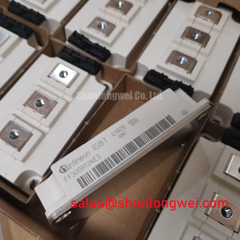
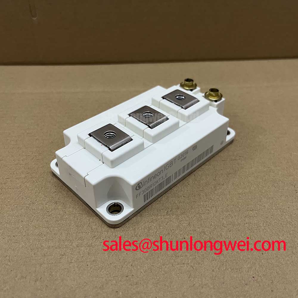
The FF300R12KT3_E from Infineon is an EconoPACK™ 3 IGBT module with a 1200.0 V collector-emitter voltage rating and 300.0 A continuous collector current rating under the specified temperature condition. Replacement assessment should connect these electrical limits to the actual cooling arrangement, terminal geometry, and switching conditions rather than treating the part number as a complete compatibility check.
| Parameter | Official Specification |
|---|---|
| Manufacturer | Infineon |
| Part Number | FF300R12KT3_E |
| Collector-Emitter Voltage (Vces) | 1200.0 V |
| Continuous Collector Current (Ic) | 300.0 A under the temperature condition below |
| Continuous collector current temperature condition | 300 A at 80°C |
| Package | Module |
| Package type | EconoPACK™ 3 |
| Configuration / Topology | IGBT Power Stage |
| Typical collector-emitter saturation voltage | 2.10 V at 300 A and 150°C |
The saturation voltage is a typical operating-point value, not a guaranteed maximum across all temperatures. For terminal assignments, mounting limits, gate ratings, and switching test conditions, consult the exact device datasheet and mechanical drawing.
Field Diagnostics & Commissioning: Thermal Paste Degradation Prevention in FF300R12KT3_E Assemblies
Inspect the thermal compound imprint across the contact area before cleaning the removed module and heatsink. Uneven transfer, displaced compound, and isolated dry areas can identify locations requiring closer examination, although the imprint alone does not establish the cause of overheating.
Design Consideration: control thermal interface material thickness through a repeatable application method matched to the selected compound and mounting instructions. Excess material can increase thermal resistance, while insufficient coverage can leave voids. Evaluate surface flatness and permitted baseplate curvature together; tightening the module harder is not an appropriate correction for a distorted heatsink.
Seat the module without rocking it, then tighten mounting screws progressively in the specified sequence. Keep heatsink mounting hardware separate from electrical terminal hardware in the work instructions because their mechanical functions differ. Following removal after a controlled trial assembly, inspect compound transfer to assess contact coverage without interpreting every visible variation as a defect.
For pulsed operation, assess junction temperature using the relevant transient thermal impedance, Zth, and the actual loss waveform. Case temperature alone cannot describe the peak junction excursion during a short load pulse. When engineers evaluate this module for industrial inverter welders or medium-frequency induction heating supplies, cooling and switching-loss compatibility should be assessed against the equipment duty cycle.
Field Diagnostics & Commissioning: Terminal Screw Engagement Depth in FF300R12KT3_E Topologies
Compare terminal screw length with the complete busbar and washer stack before tightening the electrical connections. A screw that bottoms in the threaded terminal can appear tight without producing the intended clamping force; inadequate engagement presents a different mechanical weakness.
Design Consideration: use the terminal drawing to establish allowable engagement, then account for washer arrangement, busbar thickness, and assembly tolerances. Support conductors independently so that terminal screws do not pull misaligned busbars into position. This reduces external levering loads on the terminal structure during vibration and thermal expansion without assuming anything about undocumented internal joints.
Trace each power and gate connection against the device schematic before reconnecting the DC link. Inspect conductor edges, nearby fasteners, and insulating barriers for clearance and creepage compatibility with the equipment design. Mechanical fit does not establish electrical compatibility, particularly where an existing busbar has been modified.
For sourcing comparisons, BSM300GA12DA11S is a separate candidate requiring its own topology, terminal, switching, and mounting assessment, not an assumed interchangeable replacement. Infineon’s EconoPACK™ Plus information provides related package-family context, but its mechanical instructions should not be transferred to this EconoPACK™ 3 module.
FF300R12KT3_E Circuit Protection & Reliability: Assessing Diode Recovery Softness
Capture commutation current and collector-emitter voltage together when investigating recovery-related ringing. Peak reverse recovery current and the slope of the recovery tail depend on operating current, junction temperature, and commutation conditions; a softness assessment requires the waveform and its measurement definition, not just a single peak reading.
Design Consideration: investigate whether ringing originates primarily from the power loop, diode recovery, or measurement pickup before changing components. Short, low-inductance probing connections and appropriately rated differential measurement equipment help separate genuine overshoot from probe-loop artifacts. Keep switching test conditions documented so waveform comparisons remain meaningful.
Turn-on gate resistance and an RC snubber are system-level tuning options. Increasing gate damping can reduce commutation severity while increasing switching loss; a snubber introduces its own pulse-energy and thermal requirements. Component values should therefore follow measured behavior and loss evaluation rather than a generic module-level prescription.
Practical tip: keep the commutation busbar paths compact and balanced, then verify turn-off voltage margin with a controlled double-pulse test.
Inspect the gate-emitter waveform at the module connection when checking Miller-induced turn-on and common-mode ground movement. Where negative turn-off bias is used, its magnitude and transient excursions must remain within the device and driver limits. Verify dead time using actual turn-off behavior and propagation mismatch, allowing sufficient separation to prevent simultaneous conduction without adding unnecessary diode conduction.
During system review, trace the front-end rectifier, DC link, and switching stage separately. A related module such as BSM300GA12DN2S requires an independent circuit-role assessment before consideration in a complementary switching stage; the reference does not establish suitability as a rectifier. For broader switching-device context, A Technical Showdown of Si MOSFET vs. SiC and Engineering Guide supports technology comparison, not FF300R12KT3_E-specific settings.
Transient Dynamics & Electrical Design: High-Speed Semiconductor Fuse I2t Melting on FF300R12KT3_E
Compare a proposed semiconductor fuse’s total clearing I²t with the fault path and the equipment’s protection requirements, rather than selecting it from continuous current alone. Pre-arcing I²t describes only part of interruption; arcing energy, prospective fault current, and available DC voltage also affect coordination.
Design Consideration: verify the fuse’s DC interrupting rating and operating conditions against the actual circuit. DC-link capacitor discharge can deliver fault energy before an upstream fuse clears. Fast driver protection and controlled turn-off address a different timescale from fuse interruption, so neither should be treated as a substitute for the other.
Do not infer a permissible short-circuit duration or module withstand I²t from the 300.0 A current rating. Semiconductor fault tolerance depends on the specified test conditions and protection response. Fuse coordination alone cannot establish that module case rupture will be prevented.
For commissioning, verify fault detection, driver blocking, and restart inhibition through controlled protection tests before exposing the assembly to full available fault energy. Review the fuse manufacturer’s coordination curves alongside the driver timing records, DC-link discharge path, and equipment containment provisions to establish the protection arrangement.