


Content last revised on September 29, 2026
F4-100R12KS4 Gate Transients and Switching Checks
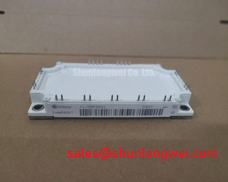
F4-100R12KS4 hardware specification card: Manufacturer: Infineon. Product category: IGBT module. The supplied product information does not establish a numerical voltage rating, current rating, or a single confirmed package designation. Use the manufacturer’s part-specific documentation and the module marking to establish those values before assessing electrical or mechanical fit.
Capture the gate-to-emitter voltage of the inactive switch while its companion switch commutates, then compare the trace with the gate driver’s intended off-state level. A brief positive excursion can indicate capacitive coupling during a fast switching edge, but the trace alone does not establish cross-conduction. Check probe placement, driver return routing, and the corresponding collector-current waveform before assigning a cause.
As a Design Consideration, keep the gate-drive return path compact and assess whether the installed driver’s Miller-clamp function holds the off-state gate at the intended potential. A negative off-state bias is another system-level option, not a specified requirement for F4-100R12KS4. The driver settings must remain compatible with the module’s verified gate limits. Review the gate resistor, clamp connection, and driver supply behavior together; changing one without measuring the resulting switching waveform can obscure the original fault.
At turn-off, busbar and connection inductance can raise the voltage seen by the switching device above the DC-link voltage. A Design Consideration is to minimize the commutation loop and evaluate laminated busbar routing where the equipment layout permits it. Measure the switching peak at the module terminals under representative operating conditions, then assess it against the verified device rating. Probe bandwidth and grounding matter: a long probe ground lead can make a transient appear larger or differently shaped than it is.
For forklift traction equipment, treat F4-100R12KS4 as a candidate for evaluation rather than an assumed replacement. Compare the original assembly’s circuit diagram, terminal assignments, gate-drive arrangement, and cooling interface. FF650R17IE4P is a separate Infineon module worth examining during a broader component comparison, but its electrical ratings and physical fit must be assessed independently; the two part numbers do not establish interchangeability.
Braking Energy and Thermal Cycling in the Installed Drive
Record the DC-link voltage during a controlled deceleration and correlate any rise with the braking command, resistor current, and module temperature trend. This distinguishes a braking-path problem from a gate-drive or cooling issue more reliably than a fault code alone. Do not assume F4-100R12KS4 contains a braking switch: establish the fitted module’s circuit configuration from its part-specific schematic before tracing the braking path.
A braking transistor and resistor, whether located within the power assembly or elsewhere in the drive, must be evaluated against the motor’s deceleration duty and the energy returned to the DC link. As a Design Consideration, examine both an individual stop and repeated stops; a resistor can cool between isolated events yet accumulate heat during frequent operation. The allowable duty, protective response, and cooling arrangement belong to the complete drive design, not to an assumed rating of this module.
For traction and battery-connected systems, the same thermal review should include motoring and regenerative operating periods. Bidirectional power flow can change which devices dissipate most heat over a work cycle. Compare measured case or heatsink temperature trends with switching activity and airflow, especially when fault events follow repeated acceleration or charging transitions. A change in switching frequency can also change losses, so a frequency adjustment should be followed by waveform and temperature measurements rather than treated as a standalone repair.
The surrounding power path deserves a separate topology check. BSM100GB120DLC is another module that may appear in equipment-level component evaluations, but its place in a rectification, conversion, or drive stage depends on the actual circuit. Trace the schematic and bus connections instead of inferring a module’s function from proximity in the cabinet.
F4-100R12KS4 Transient Thermal Response Under Pulsed Load
Log the load-current pulse, its duration, and the heatsink temperature at the same time when investigating an overload trip. A heatsink reading taken after the event cannot by itself show the junction-temperature peak reached during the pulse. Check whether the event coincides with acceleration, braking, restricted airflow, or a change in the drive’s protective timing.
Transient thermal impedance describes how a device responds to power dissipation over time before settling toward its steady-state thermal condition. For F4-100R12KS4, a numerical junction-temperature calculation requires the manufacturer’s part-specific loss and thermal-impedance data, the verified circuit configuration, and a defensible temperature boundary at the mounting interface. Without those inputs, an apparently precise peak-temperature figure would not support a maintenance decision.
As an Engineering Recommendation, use the drive’s recorded current and switching conditions to estimate losses with the verified device data, then test the resulting thermal model against temperatures measured at accessible locations. If repeated pulses are involved, include the preceding duty in the analysis rather than treating every pulse as a cold start. Inspect fan operation, filter loading, and heatsink dust before attributing a worsening temperature trend to the semiconductor alone.
Long motor cables add a different voltage stress that thermal logs may not reveal. Compare waveforms at the inverter output and, where safely accessible, at the motor terminals when investigating insulation alarms or recurring drive trips. Cable reflections can raise terminal voltage relative to the launched pulse; any filter decision depends on cable characteristics, motor insulation requirements, and measured waveforms. The discussion of resonant topologies in home appliances provides useful switching-topology context, but it does not establish a filter specification for this traction drive.
Baseplate Contact and Mounting Integrity
Inspect the module-to-heatsink contact pattern when a temperature rise persists after the cooling path has been cleaned. Uneven transfer material, debris, or a distorted mounting surface can increase thermal resistance without producing an obvious electrical fault. Check the mating surface and mounting hardware against the equipment assembly instructions before reinstalling the module.
Apply thermal interface material according to the approved assembly process and verify that the contact area is continuous rather than relying on an assumed coating thickness. As a Design Consideration, account for baseplate shape and heatsink flatness together: tightening screws cannot reliably compensate for debris or an unsuitable mating surface. Follow the specified tightening sequence and torque for the verified package and fasteners; the supplied product information does not establish those values for F4-100R12KS4.
Inspect power terminals for discoloration or looseness and compare their temperature rise during a stable operating interval. A hot connection may reflect contact resistance, cooling airflow, or current distribution, so verify the connection and its load before deciding on corrective work. In humid or rapidly changing ambient conditions, include condensation checks in the cabinet inspection and restore operation only under the equipment maker’s environmental procedure.
Maintenance note: Isolate and verify the DC link is discharged before touching the module, terminals, or mounting hardware.
For package-specific assembly guidance, consult Infineon’s EconoPACK Plus information only if the fitted package is confirmed to be in that family. Infineon’s .XT technology article discusses packaging and thermal-design concepts, but it should not be read as evidence that this particular module incorporates that technology. Finish the repair assessment with the confirmed package drawing, terminal map, mounting instructions, and measured operating temperatures for the installed assembly.