
Content last revised on October 23, 2026
FP50R06W2E3 Thermal-Electrical Optimization: Optocoupler vs Digital Coreless Transformer Practical Tuning
Disconnect the DC link, verify that stored energy has discharged, and match the FP50R06W2E3 terminal orientation to the equipment schematic before connecting a meter. For incoming inspection, record probe polarity and instrument mode alongside each reading; an unexplained difference between equivalent circuit paths is more useful than an isolated resistance value without test conditions.
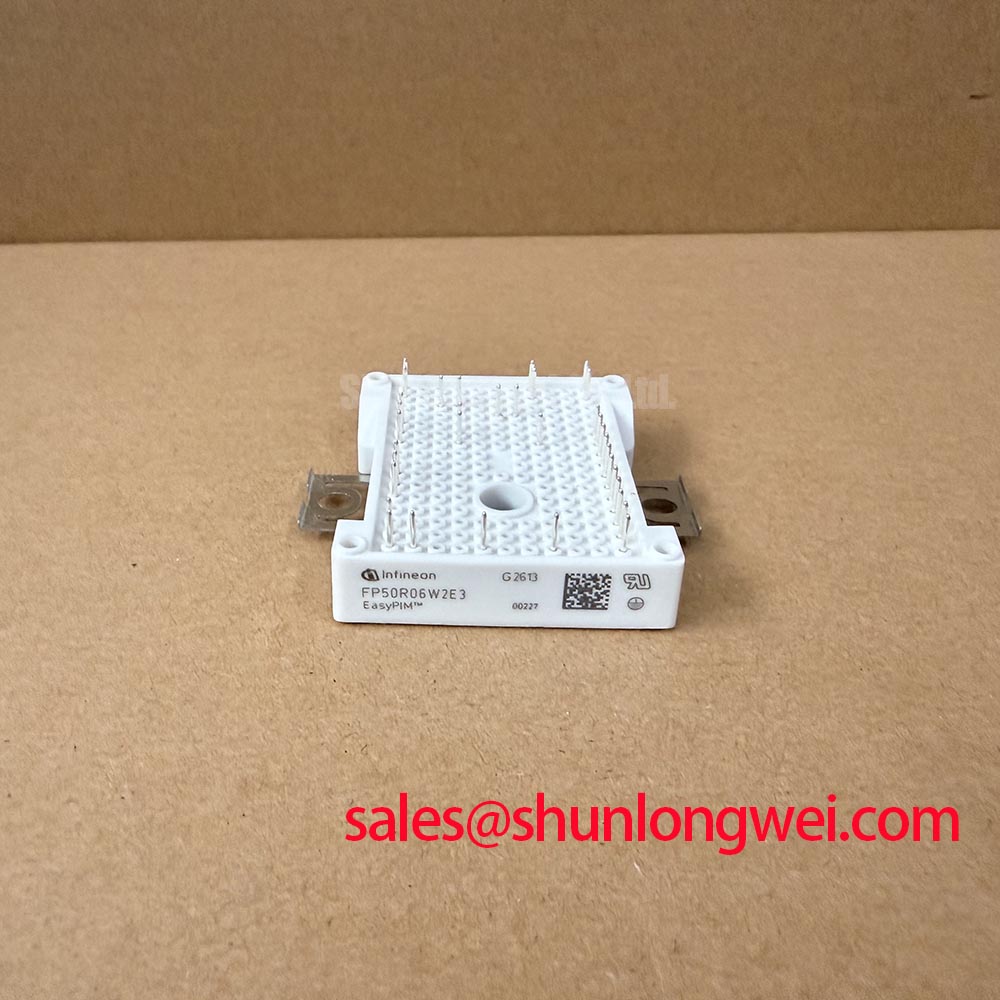
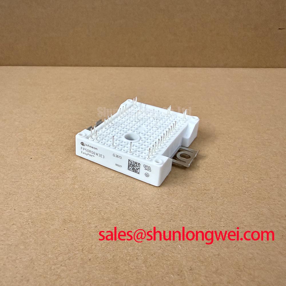
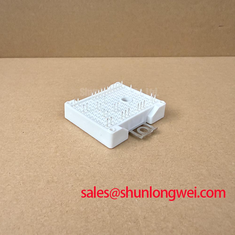
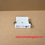
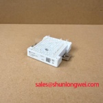
The Infineon FP50R06W2E3 is an IGBT module with a 600 V voltage rating in the 50 A current class. Its package classification is Module. These identification parameters establish the starting point for repair assessment, while terminal mapping, mounting geometry, and operating conditions determine compatibility with the equipment. The current rating must be interpreted under the manufacturer’s specified conditions, not as an unconditional continuous operating current.
💡 Bench Tip: Use ESD precautions and compare cold-state measurements with a known-good reference under the same meter settings rather than treating one diode-mode reading as a pass certificate.
Inspect the gate-driver isolation boundary separately from the module power terminals, because isolation performance belongs to the complete signal and power-supply path. Design Consideration: an optocoupler or a digital coreless-transformer driver must be assessed using its own insulation specifications, propagation characteristics, and common-mode transient immunity. Neither technology establishes an isolation rating for the FP50R06W2E3 simply by being connected to it.
Trace the control input, isolated supply, gate output, and emitter return on the actual board. Look for contamination across the isolation boundary, damaged insulation around connectors, and conductive mounting hardware approaching isolated copper. Creepage and clearance assessment should follow the applicable equipment requirements, accounting for working voltage, pollution conditions, insulating materials, and installation environment. A driver’s isolation test voltage is not interchangeable with its permitted continuous working voltage.
For suspected false turn-on, observe gate-to-emitter voltage at the module connection with appropriately rated differential instrumentation. Compare the disturbance with the switching edge of the complementary device and with the driver supply waveform. A narrow pulse can originate from capacitive coupling, shared return impedance, driver supply movement, or measurement-loop pickup. Checking these relationships helps separate an actual gate disturbance from a probe artifact before any component changes are made.
Engineering Recommendation: keep the gate-drive outgoing and return paths closely coupled, reduce unnecessary loop area, and assess damping against measured switching behavior. Gate resistance changes affect switching loss and transient stress together; the appropriate value is a system-level decision rather than a fixed prescription attached to the module’s current rating. Confirm that any protective gate clamp or active pull-down operates within the selected driver’s documented conditions.
Dead-time assessment also belongs at the driver outputs, not only in the controller configuration. Compare both gate waveforms during transitions and check whether propagation mismatch, turn-off behavior, or protection recovery reduces the intended non-overlap interval. Establish the required timing from the complete switching path across relevant operating conditions. Adding an arbitrary microsecond delay can distort operation without resolving a weak turn-off path.
When reviewing the surrounding power stage, a separate device such as BSM50GAL120DN2 should be treated as an independently specified circuit element. Its gate supply, terminal arrangement, and switching requirements cannot be transferred to the FP50R06W2E3. On an existing assembly, trace each device to its actual schematic function before deciding whether a fault belongs to the module, its driver, or an adjacent power circuit.
Manufacturer product-family information also requires careful separation. Infineon Automotive Qualified IGBTs describes a qualification category; it does not establish automotive qualification or reinforced insulation for this specific part. For incoming inspection, keep the module identity record separate from the driver insulation evidence and the equipment’s own safety documentation.
Benchtop Waveform Tuning: Mitigating Stress and Preventing Thermal Paste Degradation on FP50R06W2E3
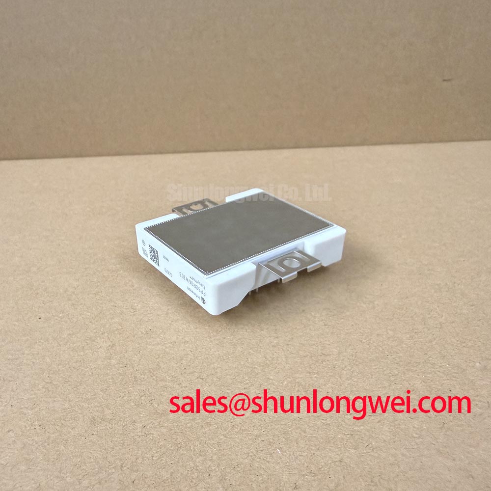
Inspect the heatsink contact surface and the specified module mounting interface before applying thermal compound. Remove residual material without damaging the mating surfaces, and check for burrs, trapped particles, or uneven contact evidence. Design Consideration: thermal interface material should fill surface irregularities without becoming an unnecessarily thick thermal barrier; the application method and permitted bond line must follow the module assembly instructions and the selected material’s requirements.
Do not use extra compound to compensate for an evidently distorted mounting surface. Check flatness against the applicable mechanical drawing and examine the contact pattern during an approved assembly trial. Uneven transfer can indicate alignment problems, contamination, or incompatible mounting geometry. Distinguishing those conditions is more useful than applying a universal paste thickness to every module installation.
Bring mounting fasteners into engagement without forcing the housing into position. Where multiple mounting points are specified, use the documented tightening sequence and torque so that clamping develops evenly. Support the assembly while connecting its electrical interface, rather than allowing a cable, connector, or conductor to impose bending load on the module. Mechanical preload and thermal contact should remain separate from the task of positioning the power wiring.
For replacement assessment, compare the complete part number and mechanical drawing before comparing headline electrical ratings. Engineers evaluating light industrial automation or multi-joint robotic articulator drives should check the equipment’s actual power-stage topology, control interface, and available cooling arrangement. The following comparison identifies the decision points without treating a related Infineon part as a drop-in substitute.
| Assessment item | FP50R06W2E3 | FS50R06KE3 |
|---|---|---|
| Manufacturer | Infineon | Infineon |
| Voltage rating | 600 V | Consult datasheet |
| Current class | 50 A — consult datasheet for rating conditions | Consult datasheet |
| Package classification | Module | Consult datasheet |
| Replacement assessment | Match the installed equipment documentation | Compare circuit, terminals, dimensions, and thermal interface |
The FS50R06KE3 is a comparison candidate, not an automatic replacement recommendation. A matching voltage or current class does not resolve differences in internal circuit connections, terminal locations, driver requirements, or mounting arrangements. Record those differences explicitly so that procurement does not mistake a cross-reference enquiry for an approved engineering substitution.
After assembly, compare temperature behavior under controlled operating conditions with the established equipment baseline. Keep ambient conditions, cooling flow, load, and measurement location consistent. A changing temperature trend can justify inspecting the thermal interface, but it does not identify paste degradation by itself. Cooling obstruction, altered switching behavior, and increased electrical connection loss should remain separate diagnostic possibilities.
Infineon’s EconoPACK™ Plus information provides manufacturer context for another module family. It should not be used to assign that family’s fastening instructions, package features, or thermal characteristics to the FP50R06W2E3. Package-specific assembly evidence is what makes a mounting procedure transferable.
Preventing Spurious Faults: Main Power Terminal Contact Resistance Guidelines for FP50R06W2E3
Measure the accessible power connection with a four-wire micro-ohmmeter only after identifying where the test current will flow and ensuring that connected circuitry cannot distort the result. Design Consideration: the measurement should distinguish the external joint from conductor resistance and semiconductor conduction paths. Place the sense leads consistently and record their locations so that later readings describe the same physical connection.
A universal contact-resistance acceptance limit is unsuitable without the connection design, material system, temperature, and manufacturer criteria. Instead, compare equivalent joints using the same setup and investigate repeatable outliers. If readings change when the leads move, first resolve contact positioning and surface access. If they change after a controlled reassembly, inspect the joint interfaces and fastening arrangement before attributing the difference to the module.
Where the equipment uses bolted busbar joints, check contact-face alignment, approved hardware, and the specified tightening procedure. Where it uses another terminal interface, follow that interface’s retention and connection requirements rather than introducing a bolted-joint procedure. Cable strain relief and conductor support should prevent vibration or thermal movement from loading the module connection. Repeated tightening without an approved method can damage the interface rather than improve it.
Thermographic inspection is useful after a safe, controlled return to operation. Compare similar connection points under comparable current and cooling conditions, and account for surface emissivity and reflected radiation. A localized hot region supports further investigation of connection loss, but a thermal image alone cannot distinguish a loose joint from restricted cooling or heat conducted from a nearby source. Correlate the image with electrical measurements and the physical connection layout.
Cold-state semiconductor checks require similar discipline. In diode mode, match the probe direction to the documented circuit and compare corresponding paths under identical conditions. Gate charging, parallel circuitry, and the meter’s test characteristics can affect observations. An unexpected reading should prompt isolation of the relevant circuit path and comparison with a reference, not an immediate declaration that a particular internal structure has failed.
Insulation testing requires its own approved procedure. Identify the intended test boundary, disconnect circuitry that cannot tolerate the test, and use the specified voltage, duration, and acceptance criteria. The module’s 600 V electrical rating is not an insulation withstand-test instruction. Likewise, a successful cold-state check does not establish switching performance, remaining service life, or complete equipment safety.
For technology context, The 1200 V CoolSiC™ MOSFET Advantage in Three-Phase Power Conversion discusses a different semiconductor technology and voltage class. It is background reading rather than evidence for FP50R06W2E3 lifetime, insulation performance, or test limits. Keep the repair acceptance record specific: terminal map, instrument settings, cold-state comparisons, connection measurements, mounting checks, and controlled operating observations.