


Content last revised on September 18, 2026
Preventing Spurious Faults: Baseplate Thermal Resistance Guidelines for FRS200BA60
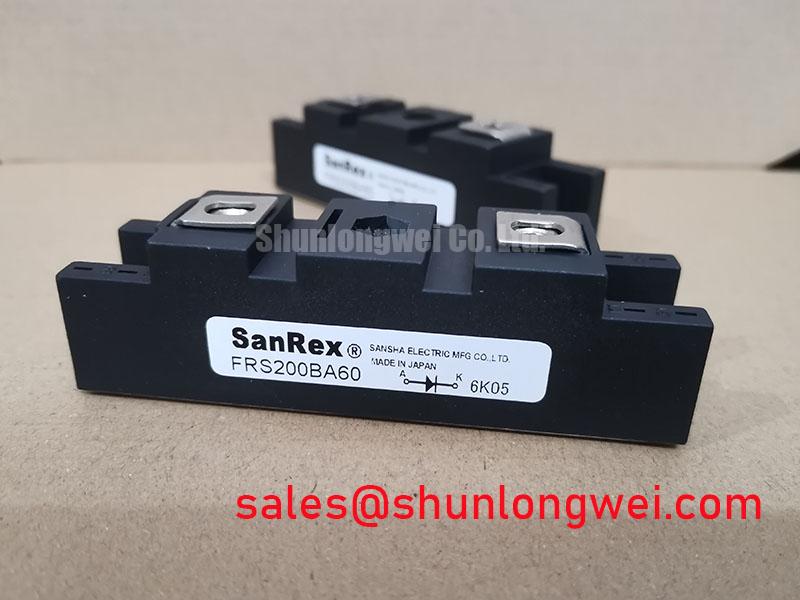
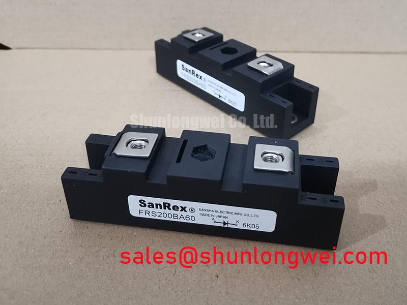
Thermal inspection starts with the mechanical interface. Clean the heatsink contact area, remove old compound, check the flatness of the mating surfaces, and confirm that the module sits without rocking before tightening the terminals. The supplied factory information identifies the housing as a SanRex Power Module but does not provide a numeric case to heatsink thermal resistance value, allowable mounting torque, compound thickness, or tightening sequence. These values must therefore be taken from the matching SanRex mechanical drawing or installation document instead of being inferred from the 200.0 A rating.
Uniform contact pressure matters because local gaps can create uneven temperature distribution across the conducting elements. During a repair, examine the removed compound for dry zones, displaced material, or evidence that one side of the baseplate carried more pressure than the other. The inspection is a Design Consideration, not a stated FRS200BA60 factory limit. The final thermal assessment should use the manufacturer’s thermal impedance data, the rectifier’s measured current waveform, ambient conditions, airflow, and heatsink temperature. If transient pulses occur during electrolyzer power changes, the system engineer should evaluate the transient thermal impedance network and confirm peak junction temperature using the permitted duty cycle.
Terminal work requires the same discipline. Verify polarity and terminal identity from the original module drawing before applying a meter or connecting busbars. Do not assume that a visually similar module has the same electrical arrangement. Cable lugs should sit squarely, with clean contact surfaces and strain relief that does not transfer mechanical force into the module terminals. The applicable terminal torque is a manufacturer installation value and is not provided in the supplied product parameters, so it should be confirmed before energization.
Fuse coordination also remains system dependent. The rectifier designer should compare the semiconductor’s documented surge withstand capability and I²t characteristic with the selected semiconductor fuse, clearing time, prospective fault current, and DC link energy. No fuse I²t table was supplied for this product, so a numerical coordination claim would be unsupported. A fuse that interrupts slowly or has an unsuitable let through characteristic may fail to protect the module during a hard short, while an unsuitable fast device may create nuisance interruption during normal current transients.
Bench Tip: Use ESD precautions and record a cold-state baseline for terminal resistance and diode-test behavior before comparing the module with a known-good assembly.
FRS200BA60 Operational Boundaries: Evaluating Reverse Recovery Charge Temperature Coefficient Limits
In a rectifier or controlled conversion stage, reverse recovery behavior can influence commutation loss, voltage overshoot, and conducted or radiated interference. The requested evaluation concerns reverse recovery charge, peak reverse recovery current, recovery time, and soft recovery behavior. None of those numeric parameters is included in the supplied FRS200BA60 factory data. They should not be estimated from the 600.0 V and 200.0 A ratings, and no temperature coefficient should be presented as an official value without the relevant SanRex curve or test condition.
When the module is evaluated in a high-current electrolyzer DC power rectifier, measure the actual commutation waveform at the module terminals using a suitable differential voltage probe and a current measurement method appropriate for the busbar arrangement. Compare the waveform at relevant load and temperature conditions. A sharp current transition, excessive voltage ringing, or increased switching loss may involve stray inductance, gate timing, source impedance, diode recovery, transformer leakage, snubber behavior, or probe setup. The observation alone does not establish a single failed component.
Temperature changes can alter semiconductor switching behavior and the resulting EMI profile. Designers should therefore repeat the evaluation after the assembly reaches its intended thermal condition, while monitoring the heatsink and electrical waveform. The system engineer must determine acceptable peak voltage and current margins against the rectifier’s DC link and commutation network. Any soft recovery factor, reverse recovery charge, or temperature-dependent limit must come from the device-specific test conditions because measurement bandwidth, di/dt, junction temperature, and circuit inductance strongly affect the result.
Gate control deserves separate verification where the thyristor section is used. Confirm the gate and cathode reference from the manufacturer drawing, inspect the trigger pulse at the module terminals, and check whether common-mode ground movement is coupling into the control wiring. A short, low-impedance gate loop and a controlled return path are Design Considerations. The final trigger amplitude, pulse width, isolation method, and negative bias policy are determined by the gate-drive circuit and the applicable SanRex limits.
For engineers comparing devices within the same equipment family, the FRS200CA100 may be reviewed as a separate SanRex product reference. It must not be treated as a direct replacement without checking voltage, current, terminal arrangement, gate characteristics, thermal interface, mechanical dimensions, and the original rectifier’s control strategy.
Transient Dynamics & Electrical Design: Evaluating Post-Surge Reverse Voltage Block on FRS200BA60
A surge review should begin with the actual current waveform and the equipment protection records. The module’s supplied official ratings establish 600.0 V rated voltage and 200.0 A rated current, but no 10 millisecond half-cycle surge current value or ITSM specification is included in the provided data. The engineer should obtain the correct surge table before checking whether a line fault, transformer inrush event, or load step is within the device’s permitted non-repetitive limit.
After a surge, do not immediately reapply reverse voltage solely because the exterior appears normal. Isolate the assembly, inspect the terminals and housing, and perform controlled static checks against the approved maintenance procedure. A diode-test reading can help identify an unexpected conduction path, but it cannot confirm dynamic blocking capability or insulation integrity. Any abnormal result should be compared with a known-good module using identical meter polarity, lead placement, and temperature conditions.
Reverse voltage reapplication requires attention to residual heat. Junction temperature may remain elevated after a high-current event even when the heatsink feels cooler than expected. The correct post-surge decision depends on the manufacturer’s transient thermal data, measured current duration, cooling system response, and the protection circuit’s clearing behavior. The system designer should verify peak reverse voltage, repetitive duty, and recovery conditions during controlled testing rather than infer safety from the nominal voltage rating alone.
Fuse selection should be reviewed at the same time. The semiconductor fuse must be coordinated with the module’s documented surge withstand and I²t data, the available fault current, and the clearing time of the complete protection chain. Since the supplied information contains no FRS200BA60 I²t table, the result should remain a verification task. Record the fuse part number, pre-arcing or clearing information when available, and the event waveform so that repeated trips can be separated from genuine semiconductor damage.
Field Diagnostics & Commissioning: Critical Rate of Rise of Off-State Voltage in FRS200BA60 Topologies
Commissioning should capture the off-state voltage at the module terminals, not only at a remote controller or bus capacitor. A fast voltage transition can couple through parasitic capacitance and produce an unintended trigger condition, especially when the gate return and power return paths share impedance. The FRS200BA60 product information supplied here does not state a critical dv/dt limit, so the engineer must obtain the manufacturer’s value and test condition before declaring a switching waveform acceptable.
RC snubbers and series saturable reactors are application-level design elements. Their values must be selected from measured overshoot, commutation frequency, load current, stray inductance, capacitor pulse capability, resistor dissipation, and the required transient response. The correct Design Consideration is to reduce unwanted voltage stress and false triggering while preserving the intended rectifier waveform; it is not appropriate to prescribe a fixed Rs or Cs value without circuit measurements.
During troubleshooting, use a properly rated differential probe, maintain a short measurement loop, and compare the suspected branch with an operating reference branch. Look for correlation between off-state voltage transitions, gate disturbance, current imbalance, and heatsink temperature. An apparent dv/dt issue may also reflect incorrect terminal identification, a damaged trigger circuit, poor grounding, measurement pickup, or an unsuitable commutation network. The waveform should be checked under the equipment’s actual switching and loading conditions.
Gate-drive layout and common-mode noise control should be reviewed before changing protection components. Minimize parasitic loop area, keep the gate reference consistent with the cathode reference, and verify isolation barriers under the required operating voltage. These are Engineering Recommendations; the final arrangement must be validated against the module documentation and the complete rectifier test plan. The Precision Gate Drive Design guide provides additional application context for evaluating gate-loop behavior and transient control.
For electrolyzer rectifier service, maintain a commissioning record containing the module identification, measured cold-state readings, terminal map, heatsink condition, fuse data, bus voltage, load waveform, and protection events. The Lithium Iron Phosphate battery storage chemistry reference may be relevant when the rectifier is connected to an energy-storage subsystem, but its operating requirements should not be assumed to define the FRS200BA60 limits. Final acceptance remains dependent on the original equipment specification, SanRex documentation, and measured system behavior.