

Content last revised on October 7, 2026
Field Diagnostics & Commissioning: DC-Bus Layout for MDF250A20M
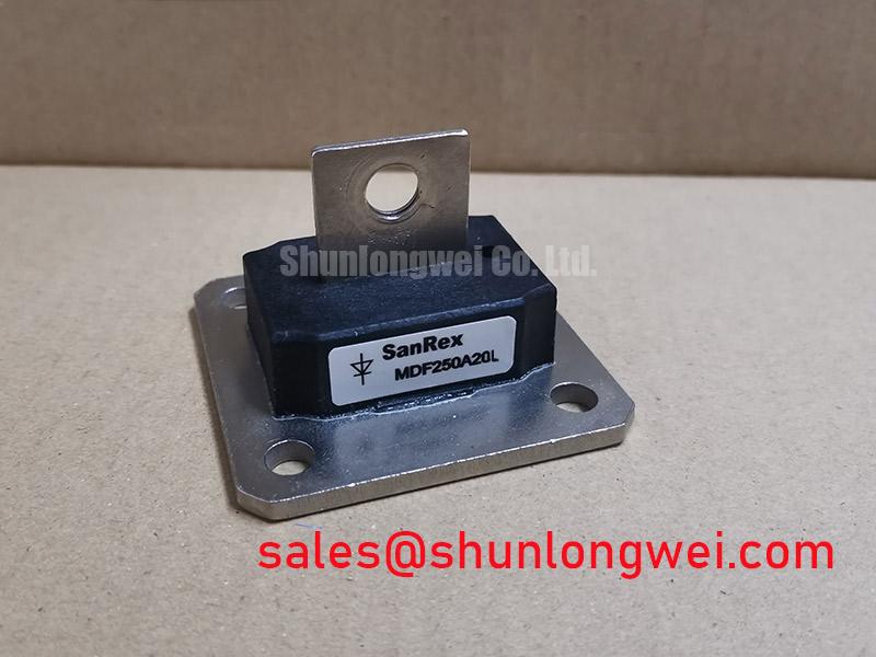
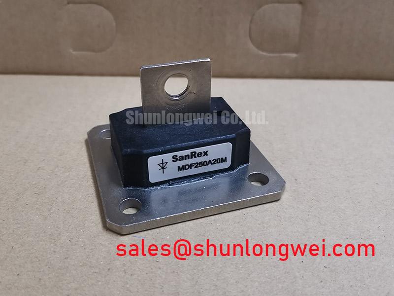
With the drive isolated and its DC link discharged, compare the installed unit’s terminal arrangement and nameplate with the replacement documentation before removing busbars. MDF250A20M is listed as a SIRECTIFIER IGBT module with a 250 A rated current and a three-phase module package (Official Specification). Its voltage is described only as a “Standard Industrial Rating”; no numerical voltage rating is provided here. Obtain the original datasheet and equipment schematic before approving a DC-link voltage or an electrical substitution.
Record where each busbar, phase connection and control lead lands before dismantling the assembly. After isolation, inspect mating surfaces for heat marks and loose joints, then compare cold-state measurements with an established service procedure or a known-good assembly. A static meter reading alone cannot establish switching performance or confirm every internal connection.
Design Consideration: Keep the DC-link current path compact and the outgoing and return conductors closely coupled to reduce parasitic inductance. During turn-off, inductance in that loop adds a voltage overshoot to the DC-link voltage as current changes. The system engineer should capture the resulting peak at the device terminals under representative switching conditions and check it against the verified device voltage rating. Select any snubber only after reviewing those waveforms and the complete circuit; a capacitor cannot compensate for an unidentified connection error.
Compare an alternative module, including K420A4001, by terminal map, circuit topology, electrical ratings, mechanical fit and test results. Its listing alone does not establish direct interchangeability with MDF250A20M.
Transient Dynamics & Electrical Design: Isolation and Current Sharing
Trace the drive-board supply, isolator and gate-return path against the equipment schematic before energizing the repaired assembly. Isolation withstand and common-mode transient immunity belong to specified barriers and driver components; neither can be inferred from MDF250A20M’s current rating. Design Consideration: Select and verify the installed driver’s isolation arrangement and transient behavior for the equipment’s working voltages and measured switching waveforms.
If the system uses parallel power paths, compare conductor length and resistance, gate-drive routing and thermal contact on each path. A positive temperature coefficient can assist static sharing only where it is documented for the relevant devices and operating region; it does not establish dynamic sharing. Capture individual path currents during switching before treating a balanced DC measurement as sufficient. Symmetrical busbar geometry is useful for limiting path differences, but the final layout and clearances depend on the equipment design.
The surrounding power topology also matters. An upstream or auxiliary-stage device such as MBM200H45E2-H should be assessed against its own documentation rather than treated as a specified companion to MDF250A20M. For topology context, a Vienna rectifier illustrates how a three-phase front end can differ from other rectifier arrangements; identify the actual front end from the machine schematic before interpreting DC-link behavior.
MDF250A20M Operational Boundaries: High dv/dt and Cross-Conduction
Probe the off-state gate waveform at the relevant driver reference during controlled commissioning, alongside the switching-node waveform. A gate disturbance coincident with a fast voltage transition may warrant investigation of Miller coupling, driver impedance and shared return-path inductance; it does not, by itself, prove shoot-through. Compare the observation with the driver’s fault records and the expected gate timing.
Design Consideration: An active Miller clamp or a suitable off-state gate bias can be evaluated where the verified device and driver specifications permit it. Confirm gate-voltage limits, clamp behavior and dead-time at the actual terminals rather than assigning a generic bias value to this module. Keep the gate loop away from the high-current commutation path, then check the revised layout during representative switching tests.
💡 Pro Tip: Keep opposing DC-bus conductors closely coupled to limit turn-off overshoot, and verify the resulting voltage margin with measured switching waveforms.
MDF250A20M Thermal-Electrical Optimization: Regenerative DC-Bus Surges
During deceleration, trend DC-link voltage, phase current and braking commands together. A rising bus voltage can be consistent with returned motor energy, but the system schematic must establish whether a braking chopper and resistor are present. MDF250A20M’s supplied specifications do not identify an internal braking switch. If braking hardware is external, evaluate its switch, resistor energy capability and control thresholds from their own documentation and measured duty cycle.
For a possible forklift traction-controller integration, confirm the controller topology, battery voltage range, deceleration profile and physical interface before evaluating this module. Do not derive brake-resistor sizing from the 250 A module rating alone. Review the heat path from module to heatsink as well: thermal diffusivity describes how temperature changes propagate through a material, while actual assembly temperature depends on contact quality, losses and cooling. For broader application and test context, see Industrial Applications; validate this assembly against its own measured electrical and thermal operating conditions.