

Content last revised on October 29, 2026
Assembly Integrity & Layout Architecture: Implementing Braking Resistors and Chopper Transistor for FRS300BA70
- Isolate the equipment, verify that stored DC-link energy has discharged, and disconnect parallel circuit paths before checking the main terminals.
- Compare terminal markings and the equipment schematic before connecting test leads or identifying a gate-drive connection.
- Inspect the mounting surface, thermal interface, and cooling passages for contamination, uneven contact, or displaced material.
- Check the braking resistor connections and protective earth continuity before planning an energized test.
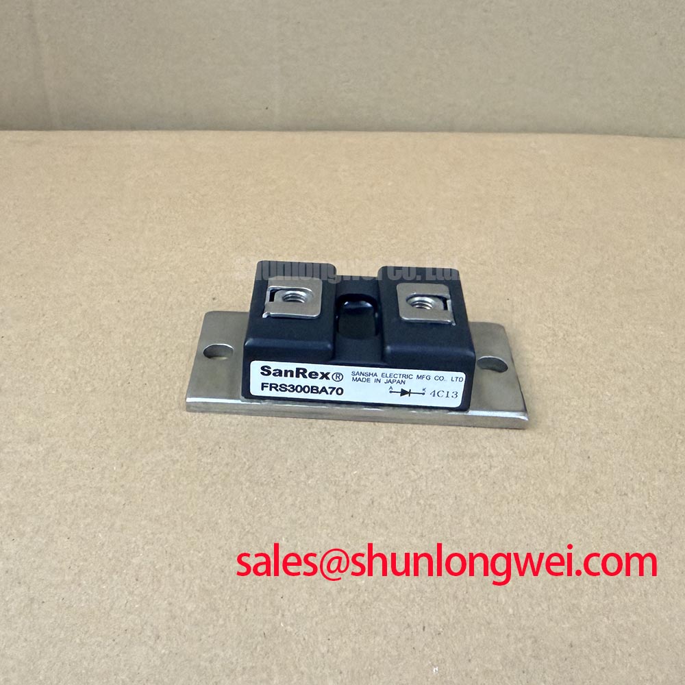
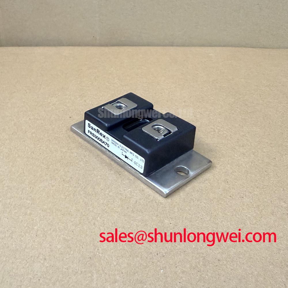
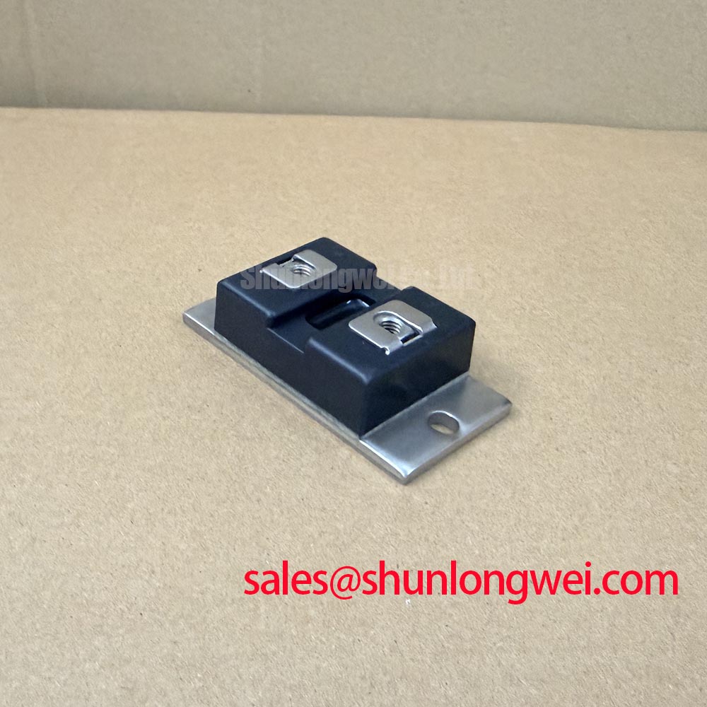
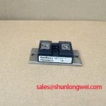
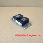
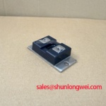
The FRS300BA70 from SanRex is identified here as a 700 V IGBT Module in a Power Module package. Maintenance planning should connect that electrical identification with the actual assembly: terminal arrangement, mounting interface, cooling provisions, and protection circuit. A matching model marking is the starting point for an equipment repair, not a substitute for checking the installed circuit.
| Product attribute | Specification | Parameter status |
|---|---|---|
| Manufacturer | SanRex | Product identification |
| Model | FRS300BA70 | Manufacturer part number |
| Category | IGBT Module | Supplied product classification |
| Collector-emitter voltage, VCES | 700 V | Official Specification |
| Package | Power Module | Supplied package classification |
| Current rating, terminal diagram, dimensions, and switching limits | Consult Datasheet | Not specified in the supplied parameter set |
Trace the braking branch from the DC link through its switching device and resistor before deciding whether the FRS300BA70 occupies that position in the equipment. Design Consideration: regenerative deceleration returns mechanical energy to the DC link; the braking chopper controls the transfer of that energy into a resistor, where it becomes heat. The resistor does not absorb energy into the DC link, and the module designation alone does not establish its circuit role.
For a braking assessment, collect the machine’s inertia, deceleration profile, repetition rate, and measured bus-voltage behavior. Engineers should select resistance, pulse-energy capability, and average dissipation together with the chopper’s electrical and thermal limits. A resistor selected only by its continuous wattage can overlook repetitive braking pulses, while an unsuitable resistance can demand excessive switch current.
Keep resistor heat away from the module’s cooling inlet and temperature-sensitive wiring. Route the braking current path to limit parasitic inductance, while maintaining clearances determined by working voltage, environmental conditions, and the equipment’s applicable requirements. Inspect resistor supports and terminal insulation for heat damage without assigning an assumed clearance or tightening torque to this package.
When evaluating compatibility with a compact industrial inverter or high-speed CNC spindle drive, compare the original assembly’s terminal map, driver interface, cooling arrangement, and protection coordination. The KS221K10 can be included in a separate hardware comparison, but it is not established here as a direct replacement. Similarly, the CM100DU-12H belongs in a separate power-stage assessment; its connection and function must follow the equipment schematic rather than an assumed complementary pairing.
FRS300BA70 Circuit Protection & Reliability: Calibrating Unpowered Bench Screening: Multimeter Diode Checks
Disconnect external paths that could influence a diode-mode reading, then record the meter polarity and terminal pair for every measurement. Engineering Recommendation: where the verified internal schematic shows an antiparallel diode, compare forward and reverse behavior with the corresponding path in a known-good assembly. Capacitors, snubbers, and connected driver components can alter readings and should be accounted for before interpreting an apparent short.
A multimeter screening result cannot establish rated blocking capability or switching performance. Gate-path resistance measurements can identify gross abnormalities after the gate terminals have been positively identified, but a handheld meter does not quantify gate leakage at the manufacturer’s specified test conditions. Avoid applying an insulation tester across semiconductor terminals without an approved test procedure.
During the same service intervention, inspect heatsink channels, fan operation, and thermal-interface contact. Design Consideration: increased switching frequency generally adds switching losses, so thermal assessment should use the actual operating conditions and manufacturer loss data rather than a presumed frequency rating. Check cooling performance at the cabinet’s expected ambient conditions, including airflow restrictions caused by filters and adjacent assemblies.
Maintenance Note: Trend terminal temperature rise and check cooling airflow during scheduled service, with all connections inspected only after safe isolation.
Set thermal-interface inspection intervals from equipment service history and manufacturer maintenance guidance rather than an invented replacement calendar. During cold-to-warm environmental transitions, inspect for condensation and follow the equipment’s drying and restart procedure. The SanRex power semiconductor resource provides the manufacturer contact point for product documentation; the broader Future of Power Electronics article offers technology context, not model-specific reliability limits.
Assembly Integrity & Layout Architecture: Implementing Mitigating Hard Switching Transients via Active Protection for FRS300BA70
Review the fault-detection path from the power terminals to the driver shutdown input before assessing hard-switching protection. Design Consideration: a short present at turn-on and a short arising during conduction produce different detection conditions. Detection blanking, propagation delay, and controlled turn-off must fit the device’s documented short-circuit capability; no numerical withstand time is established here for the FRS300BA70.
A staged soft turn-off can reduce current slew during fault interruption, but its timing must balance inductive overvoltage against continued semiconductor heating. Minimize the commutation-loop area and assess the voltage waveform with appropriately rated measurement equipment. If active clamping is used, check the clamp threshold, energy handling, and driver interaction against the complete circuit limits rather than treating the clamp as an unrestricted protective feature.
Driver isolation also needs attention during rapid common-mode transitions. Select optocouplers or digital isolators using their documented common-mode transient immunity under the circuit’s operating conditions. The general principles of galvanic isolation explain electrical separation, but isolation alone does not establish immunity to switching disturbances. Examine driver supply behavior and gate waveforms when investigating unintended switching.
Miller-coupled gate disturbance depends on collector-gate capacitance, switching conditions, and gate-loop impedance. Engineers should evaluate gate discharge and any Miller-clamp function using measured waveforms. Semiconductor fuse coordination is a separate task: compare fuse clearing behavior and let-through energy with documented circuit withstand limits, without assuming a fuse can protect the semiconductor junction during every fault.
Long motor leads introduce another measurement location: reflected-wave stress at the motor terminals. Assess cable length, switching-edge behavior, and termination conditions before selecting an output reactor or filter. Measure both the inverter-side switching waveform and motor-terminal stress so that a cable-related event is not incorrectly attributed to the replacement module.