



Content last revised on October 28, 2026
FS200R12A1T4 Operational Boundaries: Evaluating Type-2 Coordination: Protecting IGBT Modules
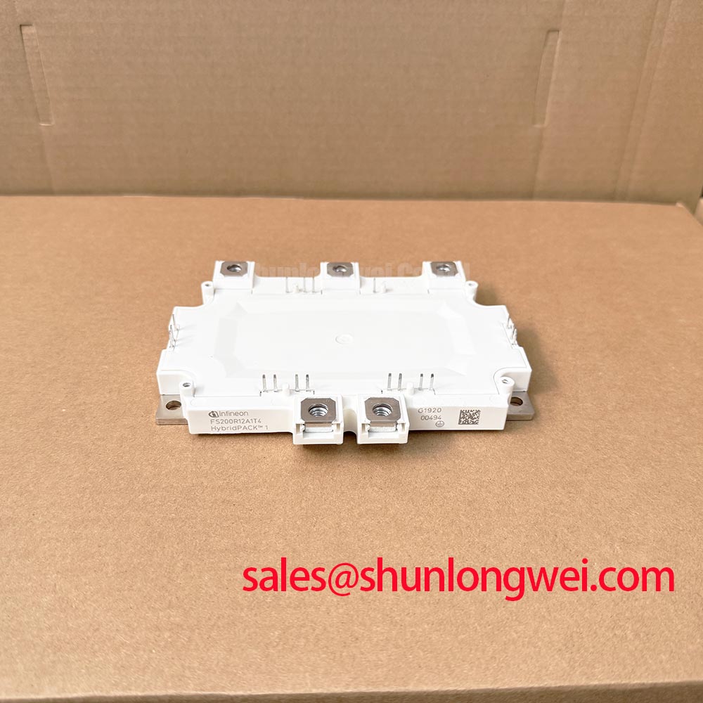
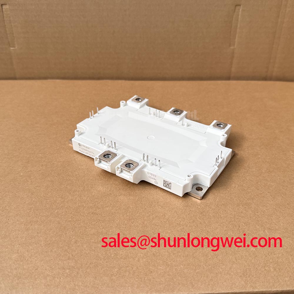
With the DC link isolated and verified discharged, compare the module terminal markings with the equipment schematic before reconnecting the gate-driver harness. For the Infineon FS200R12A1T4, the official electrical ratings supplied for this product are 1200 V and 200 A, in a Module package. These ratings establish the starting point for assessment; protection coordination, cooling conditions, and switching behavior determine whether the installation remains within its operating boundaries.
A replacement assessment should retain the original terminal mapping, mounting arrangement, and protection sequence as separate checks. A matching part number does not establish that a damaged driver board, distorted busbar, or compromised cooling interface is ready for reuse. The FS200R12A1T4 product page provides the sourcing reference, while the engineering considerations below address the surrounding interfaces without assigning undocumented characteristics to the module.
Compare the semiconductor fuse’s total clearing behavior with the complete fault-interruption sequence, not just its continuous-current marking. Design Consideration: fuse coordination must account for the prospective fault current, DC-link discharge path, circuit inductance, and the fuse manufacturer’s specified operating conditions. Total clearing I²t describes thermal let-through during interruption, but it is not interchangeable with an IGBT’s short-circuit safe operating area or permissible short-circuit duration.
The distinction matters when a fault occurs inside an energized bridge. Gate-controlled fault interruption and fuse operation serve different purposes: the driver attempts to stop semiconductor conduction, while the fuse interrupts a fault-current path within its rated capabilities. A fuse cannot be assumed to act quickly enough to protect an IGBT junction simply because it carries a semiconductor-protection designation. Nor does a favorable I²t comparison alone establish that the module enclosure will remain intact during every possible DC-link fault.
Type-2 coordination also requires careful terminology. Its established use in motor-starter coordination does not automatically confer an equivalent protection classification on a semiconductor converter. For an FS200R12A1T4 installation, describe the actual tested protection arrangement rather than claiming Type-2 performance from component selection alone. Equipment-level acceptance should address interruption, accessible hazards, and the condition of components after the specified fault test.
Trace the desaturation protection path from the collector-sensing connection through the driver’s fault output and shutdown logic. Blanking must accommodate the normal turn-on transition without masking a developing fault for excessive time. The subsequent controlled turn-off must balance fault energy against inductive overvoltage. Neither timing should be assigned a generic microsecond value: the permissible sequence depends on the applicable module characteristics, driver implementation, and measured propagation delays.
During troubleshooting, retain fault records before replacing hardware. A desaturation event can accompany an actual load fault, inadequate gate excitation, sensing interference, or abnormal switching behavior. Inspect the sensing network, driver supply behavior, and fault-latch operation together. Where waveform capture is appropriate, correlate collector-emitter voltage, gate-emitter voltage, and current so that an apparent protection event is not interpreted from a single trace.
Physical routing belongs in the same review. Keep high-energy fault paths away from low-level protection wiring, preserve the equipment’s required creepage and clearance, and inspect insulating barriers around fuse connections and busbar edges. Clearance requirements follow the equipment’s working voltage, environmental classification, and applicable standard; they are not established by the module’s voltage rating alone. The Infineon IGBT Modules & Discretes Official Portfolio is the manufacturer’s reference point for the relevant device families and technical resources.
FS200R12A1T4 Thermal-Electrical Optimization: Derating Guidelines and Practical Tuning
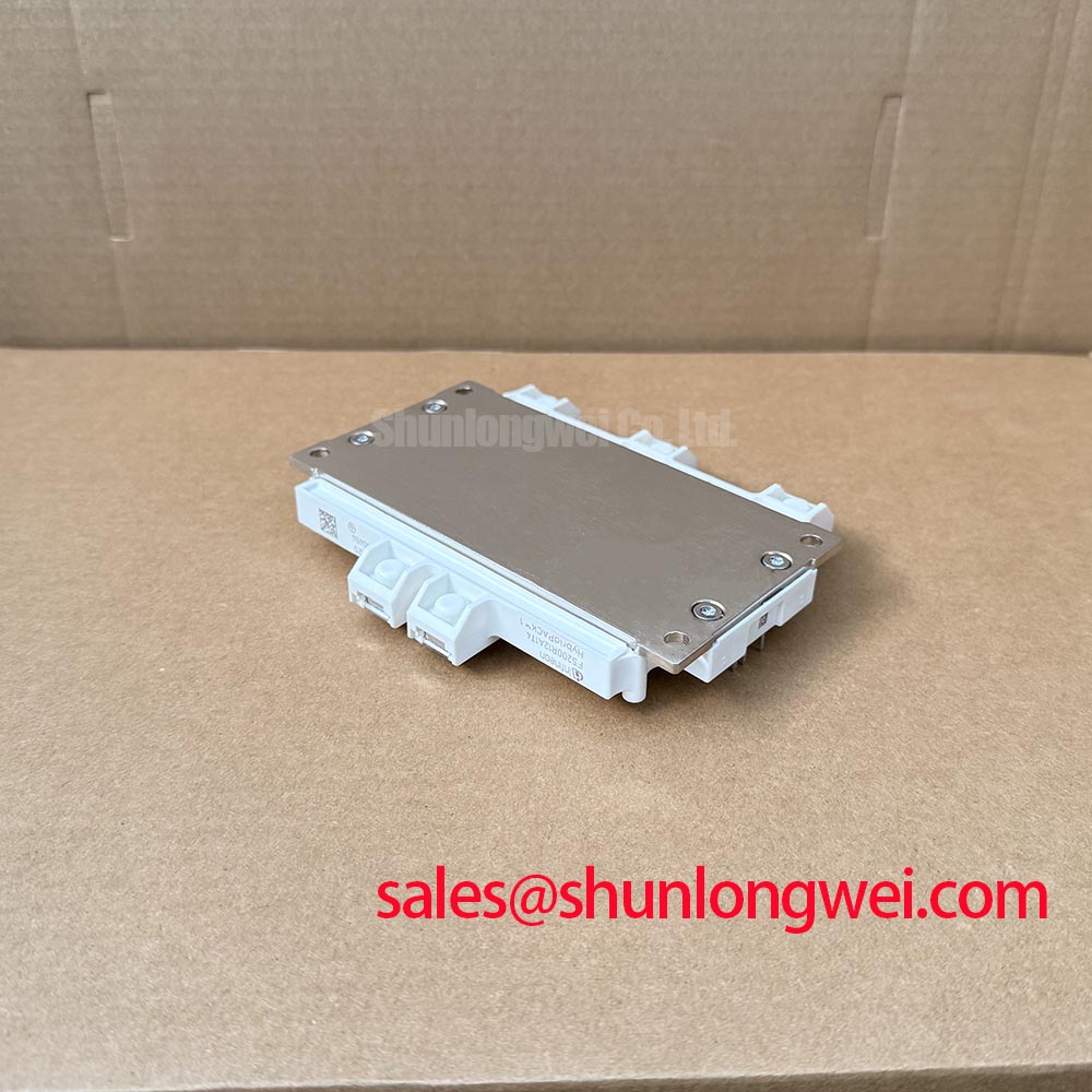
Inspect the heatsink contact surface and mounting stack before interpreting an elevated case temperature as an electrical overload. Design Consideration: cooling performance depends on contact quality, thermal-interface material, mounting pressure, coolant or airflow conditions, and the actual loss profile. The 200 A official current rating is not a substitute for checking the rating’s temperature conditions and the converter’s operating duty.
Apply the specified thermal-interface material using the module and material suppliers’ assembly instructions. Coverage, thickness, and clamping must work together: excessive material can increase thermal resistance, while incomplete coverage can leave localized contact deficiencies. Use the applicable mounting sequence and torque specification rather than a generic bolt-size rule. Tightening a mounting screw further is not a controlled remedy for an uneven heatsink or a damaged mounting interface.
For parallel operation, examine the output-characteristic curves at the intended gate voltage and current before relying on temperature-assisted current sharing. A positive temperature coefficient of collector-emitter saturation voltage can support static sharing in the operating region where that coefficient applies. It does not guarantee equal current across the entire load range, and it should not be presented as a verified FS200R12A1T4 characteristic without the corresponding manufacturer curves.
Static sharing and dynamic sharing require different checks. Similar conduction paths and cooling conditions help limit steady-state imbalance, whereas switching balance also depends on gate-loop impedance, driver timing, and power-loop inductance. Compare branch currents during both conduction and switching. A branch that shares acceptably at steady load can still carry disproportionate transient current during turn-on or turn-off.
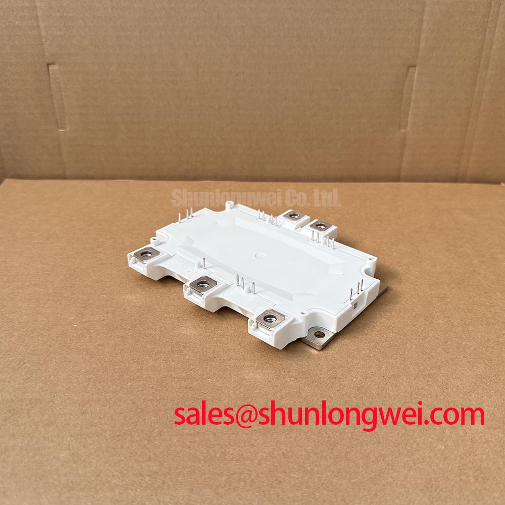
Verify each power and control terminal against the applicable connection drawing before adapting an existing assembly. Do not infer auxiliary-emitter availability, temperature-sensing connections, or internal topology from the housing appearance. When parallel branches are involved, preserve equivalent electrical paths and evaluate whether the existing driver can maintain the required gate waveform at every device. Cable routing changes made for mechanical convenience can alter the switching behavior being assessed.
Engineering Recommendation: Keep parallel busbar and gate-loop paths symmetrical where practical, then use double-pulse measurements to assess current sharing and turn-off voltage margin under the intended test conditions.
Mechanical retention should prevent busbar movement without transferring excessive assembly stress into the module terminals. Check support positions, fastener engagement, and the original locking method, particularly where vibration or thermal cycling can loosen connections. Preserve spacing after installation, including at washers, cable lugs, and insulating covers. A correct unloaded assembly drawing does not reveal whether a misaligned busbar is pulling a terminal sideways after tightening.
When evaluating industrial inverter welders or medium-frequency induction-heating power supplies, designers should compare the converter topology, switching duty, cooling arrangement, and protection behavior before accepting compatibility. The BSM50GD120DN2E3226 can be included in a separate component comparison, but it is not established here as an interchangeable replacement. Compare its manufacturer ratings, circuit configuration, terminal arrangement, dimensions, and driver requirements independently rather than treating a shared voltage class as sufficient evidence.
FS200R12A1T4 Operational Boundaries: Evaluating High dv/dt Cross-Conduction Shoot-Through Limits
Measure the off-state gate-emitter waveform while the complementary switch commutates, using a probing arrangement that minimizes pickup and references the correct emitter connection. Design Consideration: collector-voltage transitions can couple current through the gate-collector capacitance, raising the off-state gate voltage. Whether that disturbance causes unwanted conduction depends on the gate discharge path, device characteristics, driver behavior, and switching conditions.
A narrow gate-voltage excursion is not sufficient evidence of shoot-through by itself. Compare its timing with bridge current and collector-emitter voltage, and examine whether the measurement changes when probe routing is corrected. Common-mode measurement artifacts can resemble gate disturbance. Use appropriately rated measurement equipment and preserve the isolation boundaries required by the energized converter.
An active Miller clamp can provide a low-impedance discharge path when implemented with a compatible driver and suitable layout. Its effectiveness depends on where the clamp connects, when it becomes active, and the impedance between that connection and the device gate. A long shared return path can undermine the intended clamp action. Review the actual current path rather than relying solely on the presence of a clamp feature in the driver specification.
Negative off-state gate bias is another system-level option, not a universal setting for this module. Select any bias only within the applicable gate-voltage limits and driver capabilities, including transient excursions during switching. Excessive negative voltage is not a substitute for controlling parasitic coupling. The design objective is to maintain reliable off-state behavior while keeping the complete gate waveform within the permitted boundaries.
Dead time must cover the real turn-off behavior and propagation-delay variation of the installed switching paths. Too little separation can allow overlapping conduction; unnecessarily long separation can alter freewheeling intervals and converter losses. Evaluate the timing at relevant temperatures, supply conditions, and load states, including startup and fault recovery. Avoid assigning a fixed delay solely from the module’s current rating or from settings used on another bridge.
Desaturation shutdown adds another timing path that should be checked independently of normal pulse-width-modulation operation. Confirm how the driver suppresses subsequent pulses, communicates a fault, and releases its latch. Controlled soft turn-off should limit the rate of current interruption without allowing excessive fault energy. Restart logic should not repeatedly reapply switching commands into an unresolved fault merely because the controller has cleared its alarm.
For recurring gate disturbances, work outward from the local driver connection: inspect return-path sharing, connector integrity, driver-supply decoupling, and coupling from adjacent power conductors. The Precision Gate Drive Design resource provides broader context for these interface checks. Manufacturer resources from Infineon Technologies should govern device-specific limits and application guidance.
After corrective work, capture the off-state gate waveform alongside current during the switching transitions that previously produced the disturbance. Verify that the improvement persists through the intended operating range and that protection shutdown still functions correctly. Retain those traces with the driver revision, busbar arrangement, and test conditions so that subsequent FS200R12A1T4 service work can reproduce the validated configuration.