
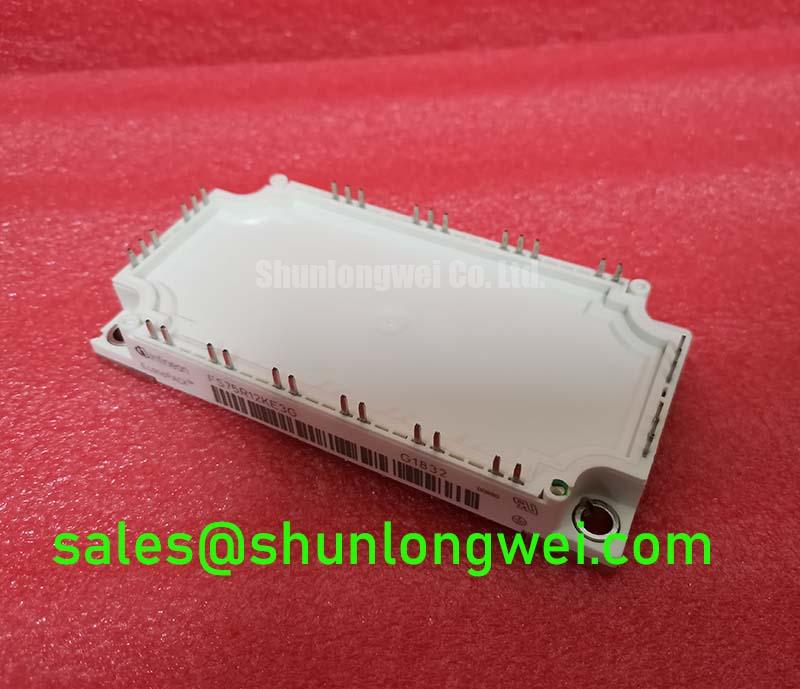
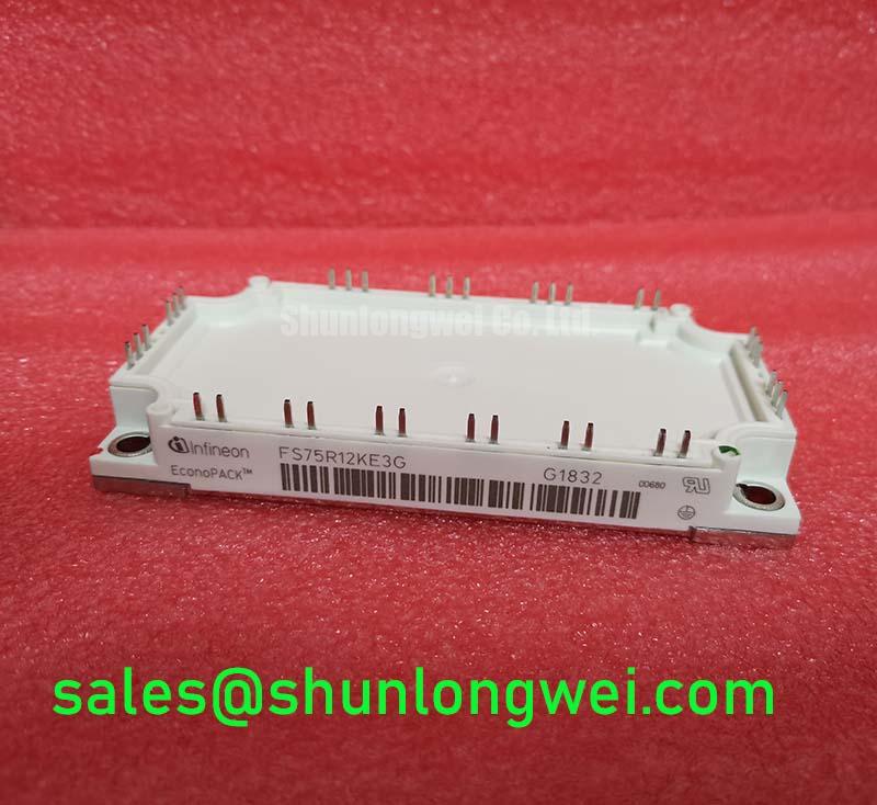


Content last revised on September 29, 2026
FS75R12KE3G Circuit Protection & Reliability: Calibrating High-Frequency Common-Mode Bearing Current
Probe the inverter output at the module terminals and motor terminals during a controlled switching test; a spike that grows at the motor end points toward a cable-and-load interaction that a DC-link measurement alone will miss. On a long motor lead, reflected voltage waves can produce terminal peaks approaching twice the incident step under unfavorable impedance conditions. That is a transmission-line Design Consideration, not a guaranteed spike level or an additional rating for FS75R12KE3G. Record the probe location, cable arrangement, switching state, and DC-link voltage with each trace so the waveforms remain comparable after a wiring or filter change.
Compare the measured motor-terminal peak with the motor insulation limits supplied by the equipment documentation. If an output filter or common-mode choke is under consideration, evaluate it against the measured differential-mode overshoot and common-mode current separately: the devices address different portions of the waveform. Filter selection also has to account for drive control behavior and heating under the actual load. Keep the module’s power connections compact to limit switching-loop inductance, then check peak collector-emitter voltage at the module during turn-off against its 1200 V Official Specification. The system engineer must set the operating margin from those switching measurements rather than from the static voltage rating alone.
Bearing-current complaints call for measurements beyond the module pins. Compare shaft-voltage or bearing-current observations with output common-mode voltage while checking motor grounding, cable shielding, and the return path specified by the machine builder. A noisy shaft waveform does not, by itself, identify a defective IGBT. At incoming inspection, use the approved terminal drawing to identify each gate, emitter, and power connection before comparing cold diode-mode readings with a documented known-good unit. A handheld meter provides a useful consistency check, but its diode test cannot verify high-voltage blocking or insulation withstand.
💡 Bench Tip: Keep the gate terminals protected from electrostatic discharge and record cold diode-mode readings in both probe directions for comparison with the same terminal pairs on a known-good module.
Preventing Spurious Faults: Thermal Paste Degradation Prevention and Mounting Guidelines for FS75R12KE3G
Inspect the heatsink contact pattern after a controlled mounting trial; dry islands or heavily displaced paste can indicate uneven contact before a thermal fault appears in operation. Clean the mating surfaces using the equipment’s approved method, check for burrs and trapped particles, and apply the specified thermal interface material as a continuous, controlled layer. Paste-thickness targets, baseplate curvature allowances, screw order, and final torque belong to the module mounting documentation and the heatsink design. An arbitrary thickness or fastener torque should not be treated as an Official Specification for FS75R12KE3G.
Seat the module evenly and tighten its fasteners in the sequence required by the applicable mounting instructions. A visible paste bead at an edge does not prove uniform contact beneath the full mounting area. Where a repeatable thermal symptom follows reassembly, compare heatsink temperature, load current, cooling conditions, and the timing of the fault with the previous installation. Transient heating needs particular attention during acceleration and braking: a steady heatsink reading can conceal a shorter junction-temperature peak. Use the manufacturer’s applicable transient thermal-impedance data and the measured load profile for that assessment; the 75 A Official Specification alone cannot establish pulse-temperature margin.
Gate-drive faults can resemble thermal trouble. Capture gate-emitter and collector-emitter waveforms at the module connection during turn-on and turn-off, using a measurement setup rated for the circuit. Driver source and sink capability must accommodate the switching demand of the installed module and the chosen gate network. As a Design Consideration, adjust the external gate resistance only after observing both switching loss and ringing: stronger damping may reduce oscillation while changing transition time and dissipation. Keep the gate and emitter return paths close together, because shared or extended wiring can introduce voltage error at the driver even when the static gate connection tests correctly.
On a bridge-leg repair, inspect the driver’s dead-time behavior while viewing both device commands and the resulting output transition. Apparent simultaneous conduction warrants checks of propagation delay, turn-off behavior, and unintended gate rise during the opposing device’s transition. Collector-gate coupling through the Miller region can contribute to that rise; any active clamp or other gate-protection function must be evaluated as part of the installed driver circuit, not assumed to be present inside this module. ⚠️ Field Alert: Disconnect and verify the DC link is discharged before moving gate leads or reseating the module.
Field Diagnostics & Commissioning: Dynamic Braking Chopper Operation in FS75R12KE3G Topologies
Trend DC-link voltage and braking-command activity through a controlled deceleration; a rising link with no corresponding chopper action directs inspection toward the braking path, its controls, and its connections. Trace that path on the actual inverter schematic before assigning any braking function to FS75R12KE3G. The supplied Official Specifications establish a 1200 V, 75 A IGBT module, but do not establish an internal braking switch, resistor, or terminal map. If the equipment uses an external chopper, identify its switching device and resistor independently.
Check the braking resistor’s documented resistance, energy capacity, and thermal installation against the machine’s deceleration duty. The resistor converts recovered motor energy into heat; its selection depends on the moving load, braking frequency, permitted DC-link excursion, and cooling. An ohmmeter check while isolated may reveal an open connection or a marked resistance departure, but it does not demonstrate that the resistor can absorb repeated braking events. Likewise, a correctly timed chopper command does not prove current reaches the resistor. Correlate the command with measured link voltage and braking-path current where the test procedure permits.
For an inverter with a front-end or separate power stage, follow the energy path through the documented DC-link connections rather than assuming that modules sharing a voltage class have interchangeable duties. FZ1600R12KE3 is another module that may arise during a broader power-stage evaluation; its circuit role and terminal arrangement must be checked independently. This distinction matters during commissioning because a braking complaint can originate in control timing, the resistor circuit, DC-link sensing, or switching hardware. Record which condition changed between tests instead of assigning a single cause from the first fault indication.
Forklift and electric material-handling traction drives are possible compatibility-assessment contexts, not confirmed applications of this particular module. A technician evaluating one for such equipment should first compare the original power-stage drawing, mounting interface, terminal assignment, and cooling arrangement. Low-voltage traction architectures also call for a separate device-technology assessment; Infineon’s OptiMOS low-voltage MOSFET range illustrates a distinct device category, not a substitution recommendation for a 1200 V IGBT module.
Assembly Integrity & Layout Architecture: Implementing Derating Guidelines and Mismatched Parameters for FS75R12KE3G
Compare the gate and emitter return routing on each proposed parallel branch before energizing the assembly; unequal loop geometry can produce unequal switching behavior even when cold static readings appear similar. Keep power paths and gate-drive paths as symmetrical as the layout permits, then measure branch current and switching waveforms under controlled conditions. This is a Design Consideration for systems that parallel modules, not a claim that FS75R12KE3G is approved for a particular parallel arrangement. Infineon’s IGBT paralleling application note explains why static sharing and dynamic sharing require separate attention.
Do not infer a reliable current-sharing margin from the rated 75 A current alone. A positive temperature coefficient of on-state voltage can support static sharing under appropriate operating conditions, but the behavior must be evaluated over the relevant current and temperature range using the device data. During switching, gate-loop inductance, driver impedance, external gate resistance, and differences in power-path inductance can shift current between branches. Compare collector-emitter voltage and gate-emitter waveforms at equivalent measurement points; investigate a mismatch before increasing load. The equipment designer determines the permissible derating from measured electrical and thermal behavior.
For a replacement evaluation, compare the original module’s footprint, terminal map, driver requirements, cooling interface, and protection behavior as separate items. FS200R12PT4 can be included in a cross-model comparison, but a shared voltage class does not establish mechanical or electrical interchangeability. Verify the candidate against the original schematic and mounting drawing before treating it as an option. At incoming QA, retain the cold terminal-pair readings alongside the part identification and test conditions so a later field measurement can be compared on the same basis.
When an intermittent trip remains after mounting and wiring checks, capture the event rather than attributing it to component age. Review gate behavior, DC-link excursions, heatsink conditions, and fault timestamps together; each can change the apparent stress seen by the module. The Field Engineer’s Handbook provides a broader framework for organizing testing and failure-analysis observations. For this installation, the actionable record is the terminal map, cold baseline, mounting condition, and switching evidence measured on the actual power stage.