

Content last revised on October 25, 2026
FZ1600R12KE3 Circuit Protection & Reliability: Calibrating Thermal Cycling Margins of Braking Systems
- Isolate the DC supply, verify DC-link discharge, and disconnect external paths before comparing collector-to-emitter and gate-to-emitter resistance readings.
- Match the module marking, power-terminal positions, and gate connections to the equipment schematic before disturbing the busbar assembly.
- Inspect the heatsink contact surface, mounting hardware, and thermal interface for contamination, uneven seating, or displaced material.
- Check cooling passages and terminal insulation for dust deposits, moisture, and condensation before commissioning.
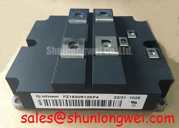
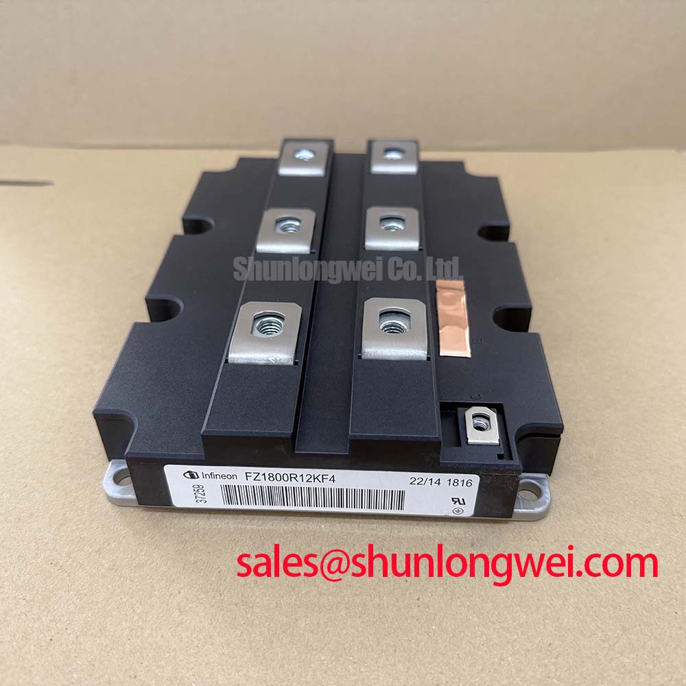
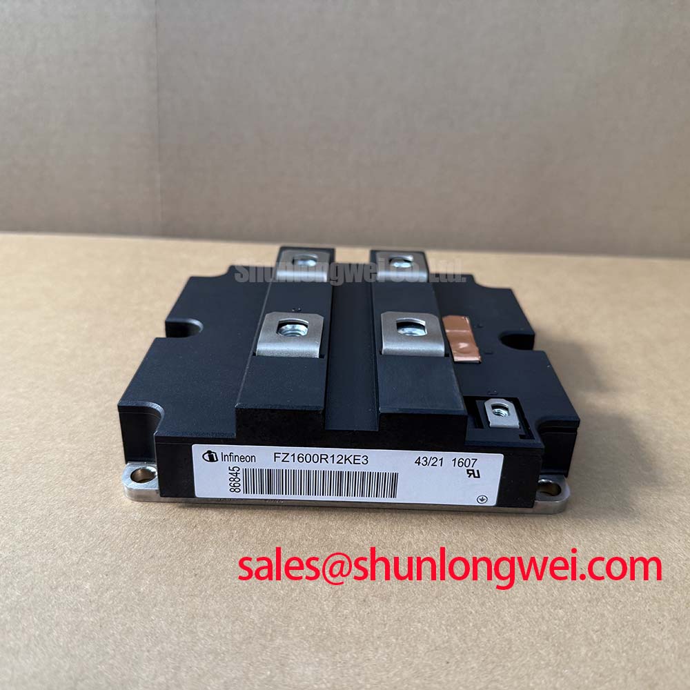
The FZ1600R12KE3 is an Infineon IGBT module with a 1200 V voltage rating and 1600 A current rating. These are Official Specification values; the specified package category is Module. Consult the datasheet for rating conditions, terminal assignments, mechanical dimensions, switching characteristics, and assembly requirements.
For replacement assessment, retain the original equipment configuration as the reference. The module, gate driver, busbar, cooling assembly, and protection circuit form an interacting power stage; matching the headline ratings is only the first compatibility check.
Trace the braking branch on the equipment schematic before assigning deceleration energy to any semiconductor or resistor. Design Consideration: A braking chopper is a system-level function; the FZ1600R12KE3 identification alone does not establish an internal braking circuit. Identify the actual switching device, resistor bank, control thresholds, and thermal protection path.
When evaluating this module within that branch, compare the braking duty with the device operating limits and the resistor manufacturer's pulse-energy and repetitive-duty curves. Deceleration energy, braking frequency, and cooling recovery determine the thermal loading. A resistor capable of surviving an isolated stop can still accumulate excessive heat during repeated operation. Record DC-link voltage and braking command together to distinguish an energy-management issue from a missing switching command.
Engineering Recommendation: Assess the MOV network separately from the braking resistor. A MOV can limit specified transient events, but it should not be assigned sustained motor-braking energy without an explicitly rated system design. Coordinate clamping behavior with bus voltage, transient energy, protective disconnection, and component temperature. Locate high-energy resistor wiring so that heat and cable movement do not compromise nearby insulation; establish clearances from the equipment's electrical and mechanical requirements.
For context on how switching topology changes current paths and device loading, Resonant Topologies in Home Appliances provides a separate topology discussion, not a qualification reference for this module. During maintenance planning, use measured temperature trends and duty records rather than assigning a service-life figure from the current rating.
Field Diagnostics & Commissioning: Long Motor Lead Reflected Wave Voltage in FZ1600R12KE3 Topologies
Compare the inverter-output waveform with the motor-terminal waveform when long cables accompany unexplained insulation stress or switching disturbances. Design Consideration: Cable-to-motor impedance mismatch can produce reflected-wave peaks approaching twice the incident voltage step under idealized conditions. Actual peaks depend on cable propagation, switching edge speed, termination, and overlapping reflections; this is not a module-specific voltage rating.
Use appropriately rated differential measurement equipment with controlled probe connections. Correlate voltage overshoot with operating current and switching transitions rather than relying on an isolated screenshot. An output choke or dv/dt filter should be evaluated against cable characteristics, motor insulation requirements, current loading, and its effect on drive control. Filter selection belongs to the complete drive system, not to the module rating alone.
At the module, keep the commutation path compact to reduce turn-off overshoot associated with busbar parasitic inductance. Review diode reverse-recovery behavior using the relevant device curves and measured commutation waveforms; neither recovery softness nor radiated-emissions performance can be inferred from the part number. The Infineon IGBT Modules & Discretes Official Portfolio provides manufacturer context for device technologies and their technical documentation.
Engineering Recommendation: Restore the thermal interface using the specified material and application method, with coverage and thickness controlled by the assembly instructions. Tighten mounting screws progressively in the prescribed cross-pattern sequence and to the documented torque. An arbitrary grease thickness or generic screw torque can undermine an otherwise correct electrical repair.
Maintenance Note: Monitor terminal temperature trends and keep cooling passages clear, investigating changes under comparable load conditions before returning the equipment to unrestricted service.
Benchtop Waveform Tuning: Mitigating Stress via High-Speed Semiconductor Fuse I2t Melting on FZ1600R12KE3
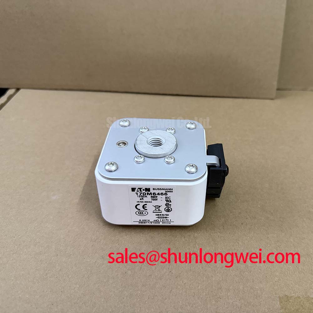
Separate fuse interruption duties from gate-driver short-circuit protection before changing either protection setting. Design Consideration: A semiconductor fuse limits fault energy within its specified operating conditions, while driver protection acts on the switching device during a fault. Fuse melting I²t alone does not establish that an IGBT will survive until interruption.
Evaluate total clearing I²t, peak let-through current, DC interrupting capability, and circuit time constant using the fuse manufacturer's coordination information. Compare these with the applicable module fault limits and the equipment's prospective fault current. Include stored DC-link energy and the fault location: a fuse upstream of a capacitor bank does not necessarily intercept the capacitor's immediate discharge path.
During controlled commissioning, capture the fault-detection signal, gate waveform, and collector-emitter voltage with a suitable measurement arrangement. Review detection delay, controlled turn-off behavior, and voltage overshoot together. Reduce commutation-loop inductance where practical, while preserving required electrical clearances. Any protection adjustment should be validated through the equipment's approved test procedure rather than by deliberately creating an uncontrolled short circuit.
Fuse coordination cannot, by itself, guarantee prevention of module-case damage. Keep enclosure containment and service isolation within the equipment safety assessment. If parallel modules are present, assess static and dynamic current sharing from their documented characteristics, symmetrical connections, driver behavior, and cooling balance; do not assume temperature dependence automatically equalizes all operating conditions.
FZ1600R12KE3 Operational Boundaries: Evaluating Main Terminal Pinout Mechanical Alignment Limits
Offer the busbar to the module terminals without tightening the screws and check that every contact seats without forced alignment. Engineering Recommendation: Correct the support geometry before fastening; terminal screws should establish contact pressure, not pull a displaced busbar into position. Check screw length, usable thread engagement, washer arrangement, and tightening requirements against the mechanical assembly documentation.
Support external conductors so that vibration, thermal expansion, and cable weight do not load the module terminals. Inspect contact faces for contamination and uneven witness marks. After assembly, compare terminal temperatures under repeatable load conditions; an unexpected difference warrants checking contact resistance, loading, and cooling rather than assuming a single cause. Set inspection intervals from equipment duty, environmental exposure, and recorded condition trends.
For maintenance purchasing, the FZ400R12KS4 can be included in a separate component comparison, but it is not established here as a compatible replacement. Compare ratings, circuit configuration, mounting geometry, terminal layout, and driver requirements before any substitution. The Infineon IGBT Modules Overview supports navigation across module families.
For a proposed high-speed rail or heavy-freight locomotive traction-inverter repair, assess the FZ1600R12KE3 against the original equipment bill of materials and qualification requirements; the stated ratings do not establish rail suitability. Before energization after cold storage or a temperature transition, inspect for condensation and follow the equipment's drying and environmental-control procedure. Release the assembly only after terminal alignment, fastening records, and cooling-system checks are complete.