



Content last revised on September 29, 2026
What the AUO G150XG01 V3 Is and Its Industrial Significance
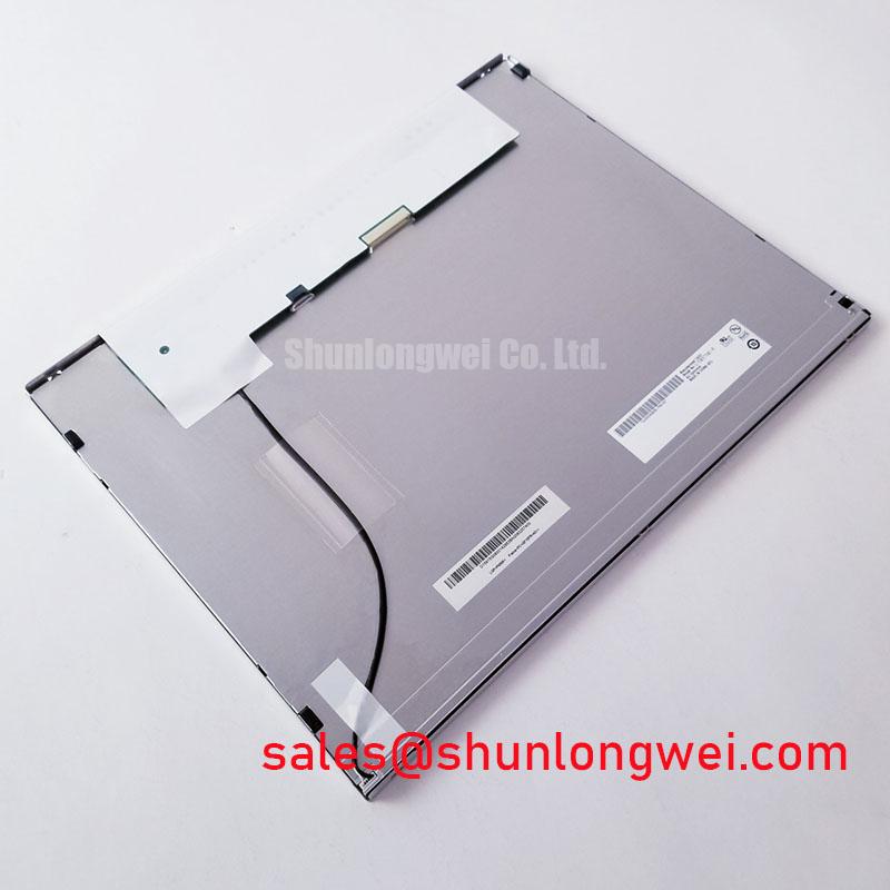
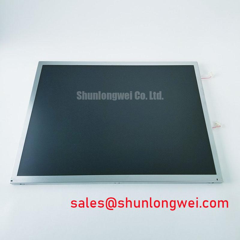
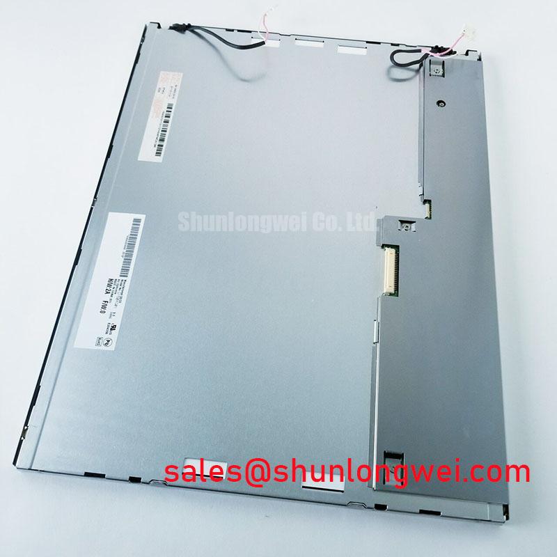
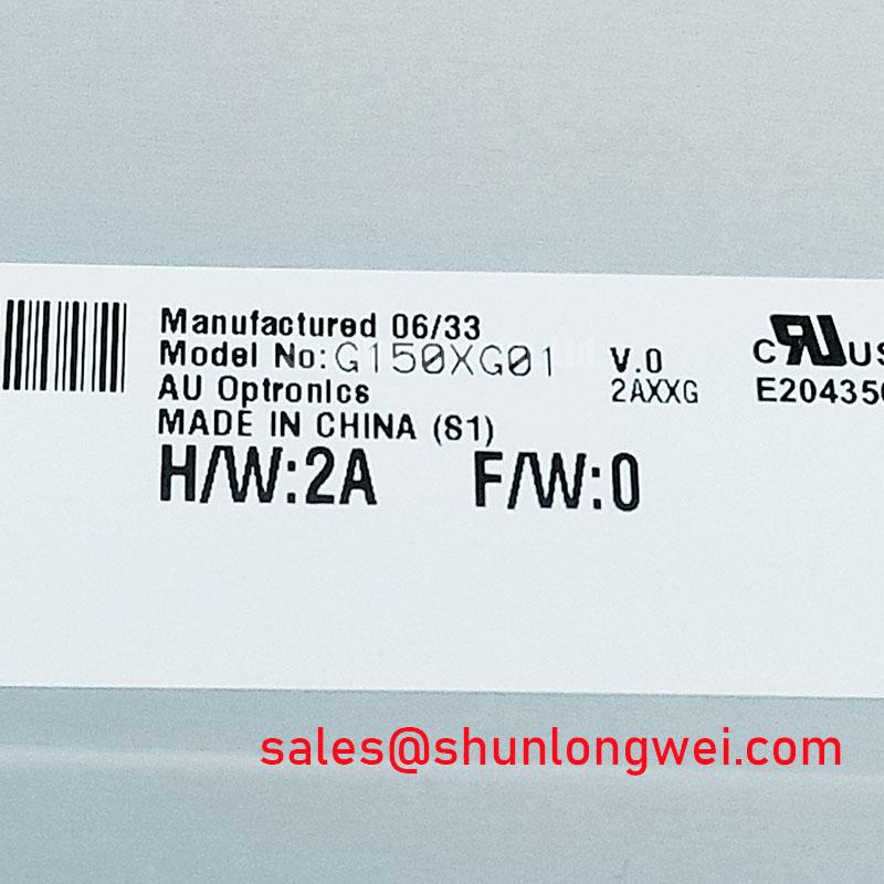
The AUO G150XG01 V3 is an industrial-grade 15.0-inch diagonal Liquid Crystal Display module manufactured by AU Optronics (AUO). Designed specifically to meet the rigorous demands of harsh operating environments, this panel integrates a standard XGA resolution of 1024 by 768 pixels with an active matrix thin-film transistor (TFT) architecture. Unlike consumer-grade displays engineered for rapid obsolescence, the G150XG01 V3 focuses on long-term availability, mechanical durability, optical stability across fluctuating ambient temperatures, and robust electromagnetic compatibility (EMC).
In modern industrial engineering, human-machine interfaces (HMIs), process control automation, medical diagnostic terminals, and embedded kiosks require display units that can operate continuously under 24/7 duty cycles. Commercial displays frequently fail in these installations due to thermal degradation, inadequate mechanical stiffening, backlighting failure, or rapid phase-outs of core silicon. The development of Liquid Crystal Display Technology tailored for the industrial sector directly solves these reliability challenges. The G150XG01 V3 delivers a standardized 4:3 aspect ratio, which remains the foundational format for thousands of industrial software platforms, legacy CNC interfaces, programmable logic controllers (PLCs), and supervisory control systems worldwide.
A primary value proposition of the G150XG01 V3 is its drop-in mechanical envelope and electrical backward compatibility across multiple equipment generations. By utilizing a standardized Low-Voltage Differential Signaling (LVDS) interface and an integrated White Light Emitting Diode (WLED) backlight array with high mean time between failures (MTBF), system designers can maintain legacy chassis enclosures without incurring the costly re-tooling, PCB re-spins, or regulatory re-certifications typically required when consumer display panels become obsolete.
Furthermore, the display addresses the optical demands of challenging factory-floor environments. It combines an anti-glare, hard-coated (3H) front polarizer with a native luminance rating of 350 to 400 cd/m2 and an 800:1 contrast ratio. This electro-optical configuration ensures high readability under diffuse overhead factory illumination or direct operator task lighting without inducing visual fatigue. By bridging the gap between legacy interface standards and modern solid-state LED reliability, the G150XG01 V3 serves as an essential building block in industrial instrumentation and mission-critical visualization hardware.
Figure 1: Internal Layer Stack and Electro-Optical Architecture of the G150XG01 V3 Module
Working Principle and Electro-Optical Architecture
The operational framework of the AUO G150XG01 V3 relies on the controlled modulation of polarized light passing through a nematic liquid crystal medium, driven by an active matrix of amorphous silicon (a-Si) thin-film transistors. Functioning as a transmissive display, the panel does not emit light natively from its pixel matrix; instead, an edge-lit WLED backlight unit generates a uniform planar light field that is selectively gated, filtered, and directed toward the viewer's eye.
The structural stack consists of several precision-aligned optical and electronic layers:
- Backlight Unit (BLU): A high-efficiency WLED string positioned along the edge of an optical light guide plate (LGP). Micro-etched dot patterns across the bottom surface of the LGP extract and scatter light evenly across the active area. Advanced diffuser sheets and prismatic brightness enhancement films (BEF) collimate the emitted photons into a forward cone.
- Rear Polarizer: Linearly polarizes the unpolarized white light emitted from the backlight assembly along a fixed optical transmission axis.
- TFT Glass Substrate: Hosts the active matrix driving circuit, where every individual sub-pixel contains an a-Si switching transistor, a storage capacitor (Cst), and an Indium Tin Oxide (ITO) pixel electrode.
- Liquid Crystal Layer: Formed by a precision-injected layer of Twisted Nematic (TN) liquid crystal molecules held at a uniform cell gap (typically 3.5 to 4.0 µm) via microscopic polymer spacer beads.
- Color Filter Substrate: Aligns red, green, and blue (RGB) color filter stripes with corresponding sub-pixels, bordered by a black matrix (BM) to eliminate inter-pixel light bleed and maximize contrast.
- Front Polarizer: Oriented with its transmission axis perpendicular (crossed) relative to the rear polarizer, treated with an anti-glare chemical etching and a 3H surface hardness protective layer.
In its native unpowered state (Normally White mode), the molecular directors of the liquid crystals undergo a 90-degree continuous twist between the rear and front substrates. When unpolarized light enters through the rear polarizer, the twisted molecular helix guides the polarization vector by 90 degrees, allowing light to pass freely through the crossed front polarizer to illuminate the sub-pixel. When the display controller applies a drive voltage (VDD) across the liquid crystal layer via the TFT switch, the resulting electric field forces the liquid crystal molecules to tilt homeotropically, aligning parallel to the electric field. This disrupts the 90-degree optical rotation, causing the front polarizer to absorb the light and render the sub-pixel dark.
Electrical signal processing within the G150XG01 V3 is governed by an on-glass Timing Controller (T-CON). Incoming graphical data arrives via a 20-pin single-channel LVDS receiver. The LVDS link utilizes low-voltage differential signaling across four data pairs (RxIN0±, RxIN1±, RxIN2±, RxIN3±) and one dedicated differential clock pair (RxCLKIN±), operating with a nominal differential amplitude of 200 to 400 mV across a 100 Ω termination resistor. The T-CON deserializes these high-speed serial bitstreams, generating line-by-line gate driver pulses (Row Scanning) and multi-level analog voltage levels (Source/Column Driving) that map pixel data across the 1024 × 768 matrix at 6-bit (262,144 colors) or 8-bit Frame Rate Control (16.2 million colors) visual depth. To learn more about active-matrix substrate architectures, see the broader reference on Thin-Film Transistor Liquid-Crystal Display (TFT LCD) principles.
Key Features, Specifications, and Technology Comparison
The AUO G150XG01 V3 is defined by its robust mechanical package, balanced electro-optical parameters, and wide environmental operating envelope. Engineered for drop-in field replacement and long-lifecycle equipment designs, the module combines low power consumption with high luminance stability.
Core performance specifications include:
- Active Display Area: 304.128 (Horizontal) × 228.096 (Vertical) mm (15.0-inch diagonal).
- Native Resolution: 1024 × 768 pixels (XGA) with a pixel pitch of 0.297 × 0.297 mm.
- Luminance: 350 cd/m2 (typical), with select revisions reaching 400 cd/m2.
- Contrast Ratio: 800:1 (typical) under darkroom testing conditions.
- Viewing Angle (CR ≥ 10): 80° Horizontal (Left/Right) and 70°/80° Vertical (Up/Down).
- Response Time: 8 ms total (typical, Tr + Tf) to minimize motion blur during fast UI rendering.
- Logic Power Supply Voltage (VDD): 3.3 V nominal (3.0 V to 3.6 V operational range).
- Operating Temperature Range: -20 °C to +70 °C (operating); -20 °C to +70 °C (storage).
- Backlight Life: 50,000 hours minimum to half-brightness (L50) under continuous 25 °C operation.
To evaluate where the G150XG01 V3 fits in modern industrial display engineering, it is instructive to compare it against other industry-standard displays, such as compact industrial panels like the NL6448BC26-27, high-reliability electroluminescent modules like the EL552-256-Q1, and modern wide-aspect industrial screens like the TX20D208VM0BAA.
| Parameter / Feature | AUO G150XG01 V3 | NEC / NLT NL6448BC26-27 | Planar EL552-256-Q1 | KOE TX20D208VM0BAA |
|---|---|---|---|---|
| Display Technology | a-Si TFT-LCD (TN Mode) | a-Si TFT-LCD (TN Mode) | Electroluminescent (TFEL) | IPS TFT-LCD (Wide Format) |
| Screen Size & Ratio | 15.0 inch (4:3) | 8.4 inch (4:3) | 8.9 inch (~2:1) | 8.0 inch (16:9) |
| Native Resolution | 1024 × 768 (XGA) | 640 × 480 (VGA) | 552 × 256 (Custom) | 800 × 480 (WVGA) |
| Luminance (cd/m2) | 350 – 400 | 400 | 55 (High Ambient Visibility) | 400 |
| Contrast Ratio | 800:1 | 600:1 | 100:1 (Effective 1000:1 dark) | 1000:1 |
| Interface Type | 1-ch LVDS (20-Pin) | CMOS / TTL (31-Pin) | Flat Panel Digital Interface | CMOS / RGB Interface |
| Operating Temp Range | -20 °C to +70 °C | -20 °C to +70 °C | -20 °C to +65 °C | -20 °C to +70 °C |
| Primary Industry Use | HMI, CNC, Medical, POS | Rugged Portable Instruments | Extreme Military / Avionics | Automotive / Process HMI |
Real-World Applications, Chassis Integration, and Operating Precautions
The AUO G150XG01 V3 is widely integrated into industrial control systems, medical diagnostics, point-of-sale terminals, and automation consoles. In computer numerical control (CNC) milling centers and supervisory operator stations, the 15.0-inch 4:3 display provides the screen area required to render complex toolpath schematics, ladder logic, and multi-variable parameter lists without visual scaling artifacts. In medical equipment—such as patient monitoring stations, mobile ultrasound carts, and clinical blood analyzers—the panel's high contrast and stable gray-level transitions ensure critical diagnostic waveforms and data tables are accurately displayed.
When integrating the G150XG01 V3 into custom metal enclosures or replacement chassis, mechanical envelope tolerances and fastening torque require strict engineering control. The display module features an integrated outer sheet-metal bezel with perimeter mounting tabs. A common field failure occurs when service personnel over-tighten mounting screws or secure the panel against a non-planar chassis frame.
Figure 2: Proper Mechanical Fastening Torque and Bezel Gasketing Layout
To avoid mechanical stress that causes optical distortion or structural failure, engineers must observe the following integration rules:
- Mounting Screw Torque: When securing the M3 mounting screws into the perimeter chassis standoffs, enforce a torque limit between 0.29 N·m and 0.39 N·m (3.0 to 4.0 kgf·cm). Over-torquing twists the outer metal frame, which exerts localized compressive force across the internal glass sandwich. This induces mechanical stress birefringence, manifesting as permanent bright patches (optical mura) around the display corners.
- Chassis Planarity: The mounting plane inside the host chassis must maintain a flatness tolerance within 0.2 mm. Never pull a bowed display frame down to an uneven casting surface using screw tension; install precision shims or compliant closed-cell silicone foam dampening gaskets behind the perimeter flange to absorb chassis tolerances.
- Thermal Management: Although the WLED backlight generates significantly less heat than legacy cold cathode fluorescent lamps (CCFL), high-density LED arrays still generate concentrated thermal loads along the bottom or top bezel rail. Ensure the host enclosure provides natural convection or conductive thermal dissipation pathways to keep the edge temperature below the maximum rated +70 °C operating boundary. Localized thermal hotspots exceeding +80 °C will degrade polarizer adhesives and accelerate LED phosphorescence aging.
- Electrostatic Discharge (ESD) and Harness Grounding: The metal bezel of the G150XG01 V3 must be tied directly to system chassis ground through multiple low-impedance grounding clips or conductive gasket strips. The 20-pin LVDS harness must use shielded twisted-pair cabling with a solid ground return. Floating bezels or inadequate cable shielding expose the sensitive low-voltage T-CON logic to high-voltage transients (ESD arc discharges), causing frame loss, image corruption, or latch-up in the column source drivers.
Engineering Selection Guidelines and Field Diagnostics
When selecting the AUO G150XG01 V3 for new designs or as a replacement for legacy 15.0-inch panels, engineers must evaluate both electrical compatibility and mechanical integration. From an electrical perspective, the host processor must provide a stable 3.3 V logic rail (VDD) capable of supplying transient peak currents up to 1.5 A during initial cold-start power sequencing. The timing controller requires strict adherence to power-up sequence timing: VDD must reach its nominal voltage (3.3 V) within 0.5 to 10 ms before the LVDS data signals (RxINx) and backlight enable lines transition to active states. Violating this sequence can trigger internal CMOS latch-up in the T-CON.
In field environments, display assemblies may exhibit various failure modes resulting from power supply ripple, cable degradation, mechanical pinching, or thermal wear. Technicians can use the diagnostic matrix below to quickly isolate and resolve field issues on systems utilizing the G150XG01 V3.
| Observed Symptom | Probable Root Cause | Diagnostic Test / Measurement | Recommended Corrective Action |
|---|---|---|---|
| Completely Dark Screen (No Backlight, No Image) | Loss of 3.3 V VDD logic supply, blown input surface-mount fuse, or missing LED backlight power/enable rail. | Check 3.3 V at Pin 2/3 of the 20-pin LVDS connector. Verify LED driver input (typically 12 V) and Backlight Enable (BL_ON = 3.3 V). | Restore power rail tolerances; check for shorted T-CON input capacitors or replace blown surface-mount fuse on the T-CON PCB. |
| White Screen (Backlight On, No Visible Image) | T-CON logic is unpowered or failed; missing VDD supply to the TFT glass while the LED backlight driver remains active. | Measure VDD at panel connector. Verify that the LVDS clock signal (RxCLKIN±) is toggling at ~65 MHz using an oscilloscope. | Inspect the LVDS interface cable for loose seating, broken continuity, or bent pins. Replace damaged cabling or defective driver boards. |
| Image Flickering, Snow, or Color Banding | LVDS signal attenuation, common-mode noise coupling, or incorrect 6-bit / 8-bit FRC bit mapping configuration. | Check differential voltage amplitude across RxIN pairs (minimum 100 mV peak-to-peak). Inspect grounding braid of the LVDS harness. | Improve cable shielding, ensure 100 Ω differential impedance matching, and reconfigure the host GPU to match the panel's 6-bit/8-bit format. |
| Localized Bright / Cloudy Patches (Optical Mura) | Excessive mechanical mounting torque, warped chassis mounting boss, or pinched internal light guide assembly. | Loosen bezel mounting screws sequentially while observing optical uniformity across a solid dark-gray background pattern. | Re-torque all chassis fasteners to the 0.29 – 0.39 N·m specification; verify mounting frame flatness and install compliant silicone gaskets. |
| Vertical or Horizontal Pixel Lines Across Panel | Damaged Chip-on-Film (COF) flex interconnect or cracked source/gate driver tape carrier package due to bezel impact. | Gently apply light mechanical pressure to the outer bezel edge near the defective line to check for intermittent contact. | Indicates unrecoverable internal bond delamination or driver silicon fracture; replace the LCD module assembly. |
| Backlight Shuts Down After Several Seconds | LED driver over-voltage (OVP) or over-current protection (OCP) triggered by an open or shorted LED backlight string. | Measure constant-current LED drive loop voltage at the backlight output connector during power-on initialization. | Inspect LED harness for pinched wiring shorting to the metal bezel; replace the backlight driver board or the internal LED strip. |
By enforcing proper mechanical mounting torque limits, maintaining clean LVDS signal routing, and observing exact DC power sequencing guidelines, engineers and field technicians can ensure the AUO G150XG01 V3 operates reliably across demanding, multi-decade industrial lifecycles.