


Content last revised on September 10, 2026
Controlled Differential-Impedance Flex Routing to Suppress High-Frequency Jitter
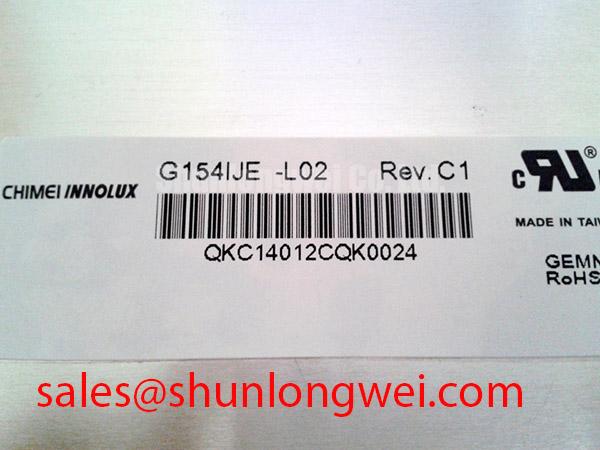
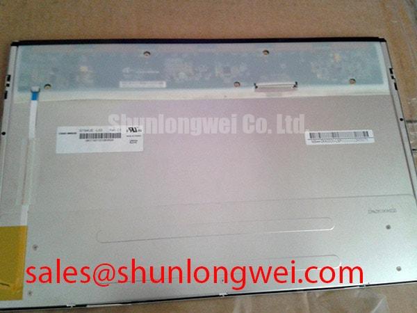
The G154IJE-L02 should be integrated only after the system engineer confirms the required display interface and logic supply from the original panel records. Do not assume a 3.3 V or 5.0 V supply, LVDS signaling, TTL signaling, JEIDA mapping, or VESA mapping solely from the model designation. These details are not included in the supplied official factory parameter set, so the original panel label, service manual, connector drawing, or approved system schematic remains the controlling reference.
When the host system uses a differential display link, controlled impedance routing is a useful Design Consideration. The designer should maintain a continuous return path, avoid unnecessary stubs, and keep the positive and negative conductors closely coupled through the flex and board transition. A nominal 100 ohm differential route with a tolerance of approximately plus or minus 10 percent is a common industry starting point for LVDS system evaluation, not an official electrical specification of this AUO panel. The final route should be checked against the transmitter, receiver, connector, and flex cable requirements as one signal path.
Pair skew should also be evaluated with the complete cable assembly installed. A commonly used engineering target is no more than 50 ps of pair-to-pair skew during early signal-integrity analysis, but the acceptable limit is system determined by the receiver timing budget, pixel clock, cable length, and electromagnetic environment. An oscilloscope or high-bandwidth differential probe can help compare the suspect display path with a known-good assembly. Look for data eye closure, excessive ringing, intermittent synchronization, or a clock relationship that changes when the flex is moved.
Split-screen images, unstable synchronization, or color groups appearing in the wrong position should not be assigned to a single cause without measurement. Verify connector orientation, cable seating, mapping configuration, supply stability, and the host transmitter settings in sequence. If the panel image changes when the cable is gently restrained, inspect the connector latch and contact alignment before changing software settings. The The Ultimate Guide to Industrial TFT LCD Technology provides broader background for evaluating TFT signal paths, interface selection, and common integration assumptions.
Power sequencing is another system-level checkpoint. The host designer should verify the panel’s required supply rail, enable order, reset behavior, and backlight control from the original documentation. A clean voltage rise does not by itself prove correct sequencing if the display interface becomes active before the panel logic is ready. Capture the supply, enable, and display clock on the same time base during startup and shutdown testing, then compare the result with the approved equipment timing requirements.
Flush-Mount Module Integration and Perimeter Gasket Shock Isolation
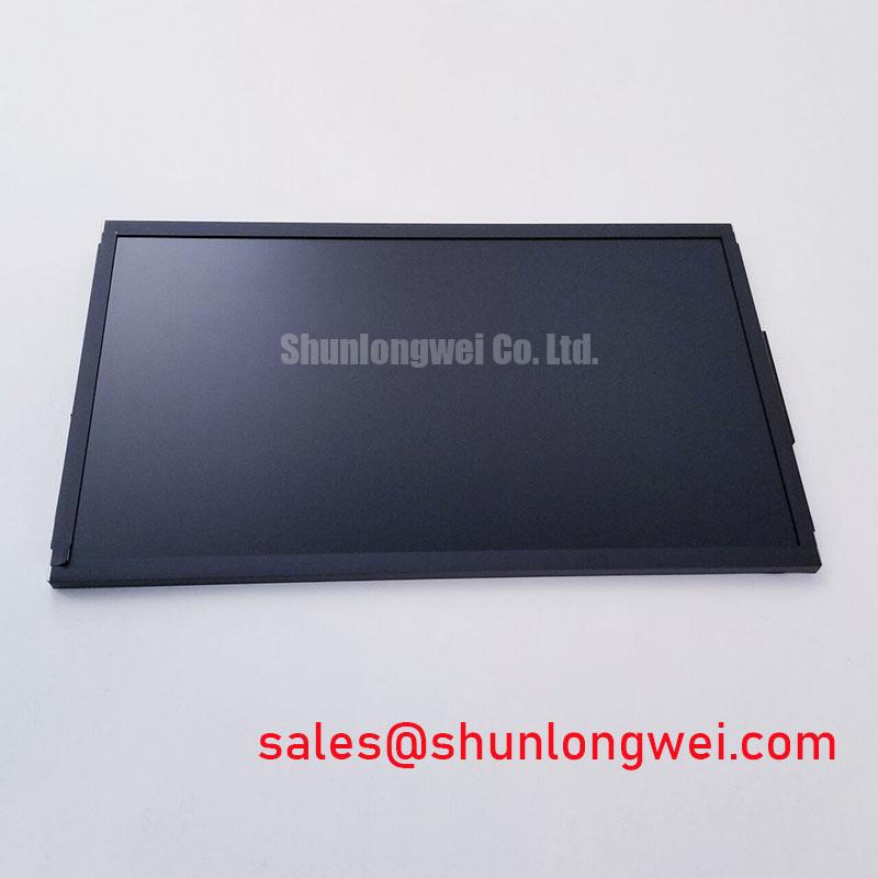
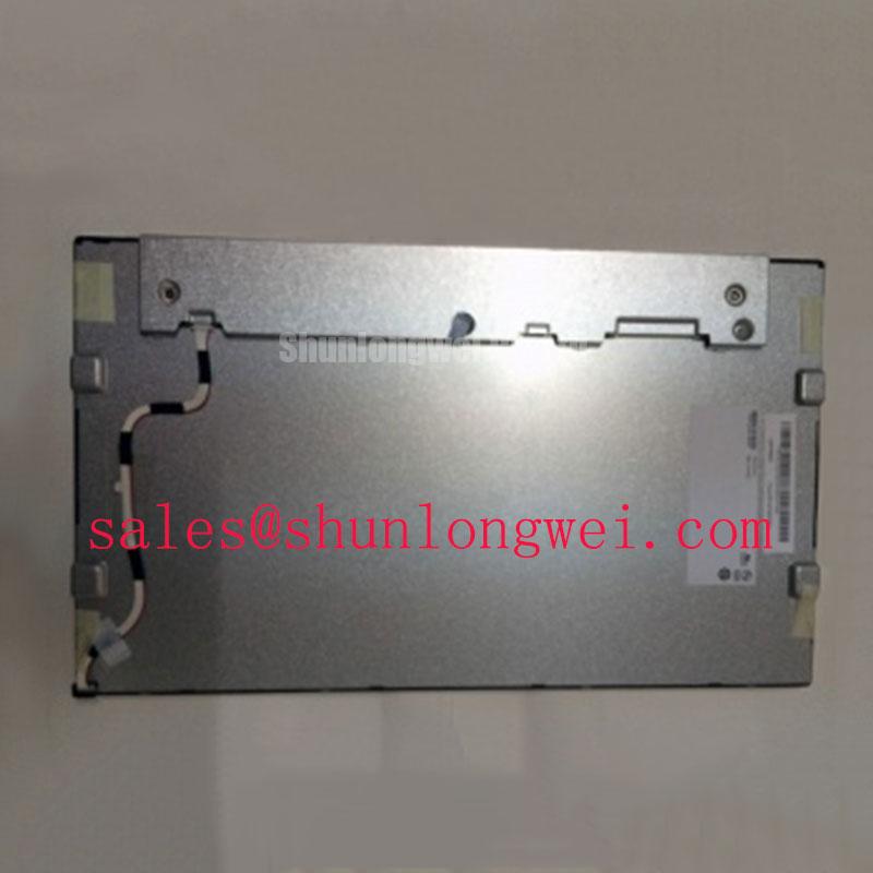
The supplied factory information classifies the product as a TFT-LCD Display Module, but it does not provide a verified outer bezel drawing, active-area dimensions, mounting-hole pattern, or installation tolerance. For an AGV or forklift telematics display, the mechanical drawing from the original equipment manufacturer should therefore be treated as mandatory. Measure the opening, mounting points, connector clearance, cable bend path, and rear component envelope before preparing a replacement panel.
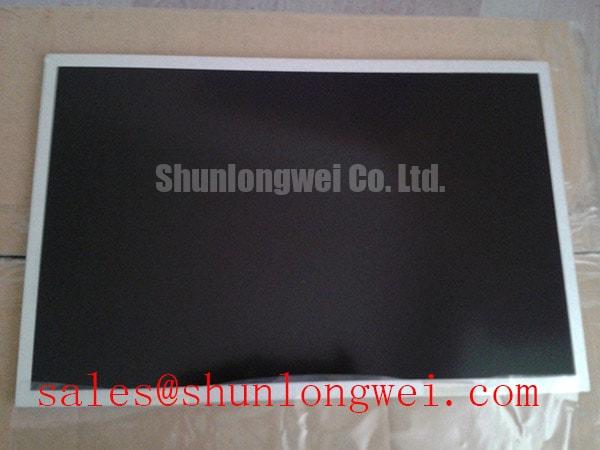
A flush-mounted installation should support the bezel evenly rather than rely on concentrated pressure at isolated corners. A perimeter gasket may be considered where the equipment enclosure requires vibration isolation or dust control, provided that its compression, material compatibility, and environmental rating are validated by the system designer. Avoid allowing the gasket, retaining frame, or fastener head to press directly against the active display area. Uneven mechanical loading can produce visible nonuniformity, temporary pressure marks, or a dark-field artifact; these symptoms require comparison with the panel in an unloaded condition.
Fasteners should be tightened in a cross pattern only when the chassis drawing specifies that method. The correct torque is determined by the fastener size, bezel construction, threaded insert, gasket behavior, and enclosure material. The commonly quoted M3 torque range of 0.35 to 0.45 N·m should not be treated as an official value for the G154IJE-L02 because no such mounting specification was supplied for this product. Use the equipment maker’s documented limit and confirm that the display remains mechanically neutral after tightening.
Display timing also needs to be checked across the intended operating temperature range. The host transmitter clock, data hold relationship, cable loss, and receiver setup margin should be evaluated together rather than inferred from the physical fit of the module. If the original system uses a TTL or LVDS transmitter, retain the approved mapping and timing configuration unless the equipment designer has completed a formal interface review. A visually correct image at room temperature is not sufficient evidence of timing margin during thermal cycling or vibration.
For vehicle-mounted equipment, the panel cable should be supported so that vibration is not transferred directly into the connector. Leave the routing defined by the approved mechanical drawing rather than forcing a tight bend near the mating interface. Connector insertion should be performed with the power removed, and the locking mechanism should be engaged evenly across its width.
Bench Tip: Use an ESD-controlled work surface and lock the flex cable perfectly flush before closing the connector latch; an angled insertion can create an intermittent image fault that is difficult to reproduce after assembly.
Flashlight Dark-Shadow Optical Diagnostic to Isolate Logic vs. Backlight Failure Modes
Incoming optical inspection should start with the panel disconnected from the vehicle or machine harness and placed on a clean, nonabrasive support. After confirming the approved host interface and power requirements, display solid white, black, red, green, and blue test fields. These fields make it easier to identify stuck or inactive pixels, horizontal or vertical line anomalies, color contamination, and regions that respond differently from the rest of the screen.
Pixel evaluation should be performed at a controlled viewing distance and under repeatable ambient lighting. Record the location of any visible defect using a panel coordinate or a photograph rather than relying on memory. A defect that appears only at a particular viewing angle or brightness setting should be documented separately from a permanently visible pixel anomaly. This approach avoids assigning a pass or fail decision to an unverified visual impression.
A flashlight dark-shadow check can help separate an image-generation problem from a luminance problem. With a suitable test image active, inspect the panel obliquely using a low-intensity flashlight and compare the darkened region with the surrounding area. If image information remains faintly visible where the screen appears unlit, the logic and pixel-driving path may still be active while the backlight or backlight control path requires investigation. If no image information is visible, continue checking the display interface, supply, enable signals, and panel drive path rather than concluding that the backlight alone has failed.
This test does not identify a specific internal failure mechanism. It cannot confirm a driver bond defect, a cell defect, or a connector fault without additional electrical and optical evidence. Use a known-good cable and host, measure the approved supply at the panel connector, and observe whether the fault follows the panel, harness, or controller. A line that remains fixed during color changes may require a different diagnostic path from an image that disappears only during startup.
Backlight service decisions must be based on the confirmed architecture of the installed unit. The supplied product data does not establish whether the particular equipment configuration uses LED or another backlight arrangement, nor does it provide a verified half-life or MTBF value. Do not apply a generic 50,000-hour brightness claim to this model without an applicable AUO document for the exact configuration. If an LED driver is present, verify its current regulation, enable polarity, dimming method, and thermal conditions from the system schematic.
Brightness uniformity should be checked after the module has reached a stable operating condition. Use the same test image, camera exposure, viewing geometry, and enclosure state for each comparison. Dark-field mura may be influenced by mechanical loading, optical surface contamination, temperature, or drive conditions. Inspect the panel both before and after bezel installation so that an assembly-related change can be distinguished from an incoming optical condition.
Backlight Inverter and LED Driver Debugging
Do not assume that the G154IJE-L02 uses a dual-channel CCFL inverter or a constant-current LED driver. The official factory information supplied for this product identifies its category and module construction but does not confirm the backlight technology, ignition voltage, channel count, PWM range, acoustic behavior, or lifetime rating. The replacement process should begin by matching the original equipment backlight controller, connector, harness, and service documentation.
If the host system contains a high-voltage lamp inverter, diagnosis should be performed with the equipment maker’s approved procedure and suitable high-voltage measurement equipment. Inspect the inverter input, enable command, output wiring, insulation barriers, and lamp connections before energizing the assembly. Audible noise, delayed illumination, repeated striking, or uneven brightness can involve the inverter, lamp circuit, connector, control signal, or mechanical installation. These observations should be correlated with measured waveforms and the known-good display path.
For an LED configuration, verify that the driver is compatible with the panel’s documented backlight input and control method. A constant-current output, enable signal, and PWM dimming input must be checked against the original system design rather than selected from a generic display controller menu. Excessive ripple, incorrect polarity, or an unsuitable control level can produce flicker, startup cycling, or reduced luminance. The driver’s thermal environment should also be evaluated inside the final AGV or forklift enclosure.
High-frequency switching in an inverter or LED driver can radiate into the display data cable. Keep the power switching loop and display signal route physically separated where the approved mechanical design permits, and provide a defined return path for high-frequency currents. When an image fault appears only while the backlight is enabled, compare the display clock and differential data with the backlight disabled and enabled. This A/B measurement can reveal coupling without presuming that the panel itself is defective.
Backlight lifetime, brightness half-life, FIT rate, single-event behavior, cosmic-ray effects, altitude derating, EMC compliance, and insulation reliability are not established by the supplied product parameters. They should not be presented as guaranteed characteristics of this module without the relevant manufacturer document, qualification report, or applicable standard. The panel itself also cannot be described as independently certified for whole-equipment EMC performance. Final suitability for an AGV or forklift telematics display depends on the complete enclosure, controller, harness, power system, vibration environment, and documented validation results.
Before returning the unit to service, repeat the solid-color inspection, confirm stable startup and shutdown, check the connector lock, and inspect the bezel for uneven pressure. Store the recorded panel identity, host configuration, optical observations, and measured supply conditions with the maintenance record so that later troubleshooting has a reliable comparison point.