Content last revised on October 24, 2026
Thermal Cycling Degradation of Polarizer Adhesives & Sealant Gasket Integrity
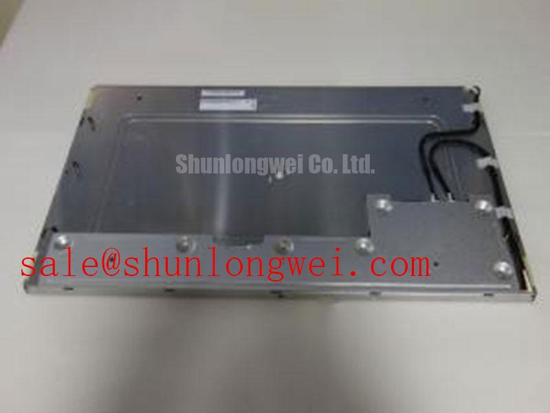
Manufacturer: AUO | Model: G238HAN01.3 | Class: LCD Display | Resolution: 1920(RGB)×1080 | Brightness: 600 cd/m² Typ. | Interface: LVDS, 2 ch, 8-bit, 30 pins
When an AGV or forklift display shows slow image transitions after a cold start, record the panel temperature, startup response, and gray-level transition behavior before opening the enclosure. The G238HAN01.3 uses an AHVA, normally black, transmissive panel with a typical 14 ms G to G response time. That figure is a room-condition specification and should not be treated as a guaranteed response value across an unverified industrial temperature range.
For equipment exposed to sub-zero storage or rapid thermal changes, the practical concern is the interaction between liquid crystal viscosity, polarizer bonding, perimeter sealing, and mechanical compression from the display frame. A design validation program may use a controlled thermal cycle between the intended equipment limits, including a proposed evaluation envelope such as −30°C to +85°C. This is a system-level test condition, not an official operating-temperature rating for this panel. Inspect the image during cold startup, after temperature stabilization, and during warm recovery. Look for slow gray transitions, temporary nonuniformity, edge haze, or changes that remain after the panel returns to room temperature.
The antiglare surface has a 3H hard coating, while the optical stack still requires even frame pressure. A rigid bezel that presses locally against the active area can convert thermal expansion into visible mura or seal stress. Designers should provide controlled mechanical support, avoid point loading near the viewing area, and verify the frame, gasket, and mounting method through thermal cycling and vibration testing. The display is specified at a typical 600 cd/m² with a typical 1000:1 contrast ratio; brightness readings should be compared at the same warm-up state and measurement geometry.
For brightness aging, the manufacturer specification identifies a WLED backlight with a 50,000-hour lifetime. Do not convert that figure into an automatic L70 or B50 prediction without the applicable test definition, driver current, thermal profile, and optical measurement method. Under a constant-current backlight driver, log luminance at scheduled intervals and separate gradual output decay from local optical contamination, driver instability, and thermal hot spots.
Single Vertical Hairline Defect & Sub-Pixel Column Driver Open-Circuit Localization
A single vertical line should first be classified with full-screen red, green, blue, white, black, and mid-gray images. If the line remains in the same screen coordinate across all colors, the pattern may point toward a column-side signal or bonding issue rather than a simple backlight variation. A 45-degree flashlight inspection with the display dark can help distinguish a surface or optical shadow from a line generated by the active matrix. Use low contact pressure around the bezel; pressing the panel can temporarily alter a marginal connection and compromise the diagnosis.
The 1920(RGB)×1080 Full HD panel uses a 30-pin LVDS interface with 2 channels and 8-bit data. Confirm the replacement harness orientation, connector seating, latch position, and cable routing before interpreting a line defect as a panel failure. An intermittent vertical feature that changes when the cable is moved may indicate a connector or harness problem, while a stable feature that survives cable substitution deserves closer inspection of the panel assembly and its bonded driver region.
For a high-EMI vehicle display system, the LVDS host layout is a system design matter. As a Design Consideration, engineers may evaluate differential routing near a controlled 100 Ω ± 10% differential environment and manage pair skew against the receiver and cable budget, with 50 ps sometimes used as a project-level starting criterion. These values are not declared electrical specifications of the G238HAN01.3. Validate the actual waveform, common-mode behavior, connector transition, and cable assembly with the selected timing controller.
💡 Bench Tip: Use ESD protection and lock the LVDS cable fully flush before applying power, because a partially seated connector can create misleading color columns or unstable image regions.
When comparing a same-size replacement path, engineers can place LM230WF9-SSC1 beside the original panel specification and check resolution, interface mapping, mounting geometry, optical stack, and backlight requirements rather than assuming interchangeability from diagonal size alone.
High-Voltage Striking Potential (1500–1650 Vrms) & Secondary Coil Insulation Testing
The G238HAN01.3 is specified with a WLED backlight, so an installed system should be evaluated as an LED backlight assembly rather than treated as a CCFL panel. The 1500–1650 Vrms striking range belongs to a CCFL ignition test concept and must not be assigned to this AUO model. Likewise, 1000:1 is listed as a typical contrast ratio, not as a PWM dimming specification for this panel.
During service, identify the actual backlight driver used in the equipment and isolate its output from the panel before performing insulation or withstand testing. The driver manufacturer determines the permissible test voltage, current limit, discharge procedure, and connection points. Applying a generic high-voltage CCFL test to a WLED assembly can damage the backlight circuit or create an unsafe test condition. For a vehicle-mounted display, inspect the backlight connector, cable strain relief, and enclosure clearances after vibration exposure.
Acoustic noise, brightness pulsing, or a backlight that restarts under dimming should be evaluated at the driver level. Check the current regulation behavior, PWM control signal, grounding arrangement, and thermal condition while observing the panel output. If a PWM dimming range is required, the system integrator should select a driver with a documented dimming method and verify visible flicker, camera interaction, and luminance stability under the intended control frequency. The panel’s listed 5.0 V typical supply voltage applies to the panel electronics; it does not define the backlight driver supply or its insulation rating.
Constant Luminance Output Control & L70/B50 LED Half-Life Reliability Verification
Measure luminance across the active area after the display reaches a repeatable operating state, then repeat the measurement near the edges and corners. The 600 cd/m² typical brightness, 72% NTSC color gamut, and 89/89/89/89 typical viewing angle values describe the panel’s listed optical performance, but installed brightness uniformity also depends on the driver, bezel opening, ambient reflections, and thermal path.
For narrow industrial enclosures, a Design Consideration is to give the backlight frame a mechanically stable heat path without transferring concentrated stress into the glass. Heat spreader rails, frame interfaces, and cushioning materials should be assessed through thermal imaging and luminance mapping. Do not infer a specific internal light-guide material or optical construction that is not stated in the product documentation. A localized hot area may result from driver placement, enclosure airflow, mounting pressure, or backlight aging, so compare thermal images with the luminance map before changing the mechanical design.
The listed 50,000-hour WLED lifetime should be tracked using the actual driver current, duty cycle, ambient temperature, enclosure condition, and cleaning exposure. L70 or B50 terminology requires a defined test method and statistical population; it should not be substituted automatically for the manufacturer’s general lifetime statement. A practical verification record can include initial luminance, color appearance, operating temperature, dimming condition, and later measurements under the same setup.
LVDS routing remains important when the display is installed near traction motors, switching converters, or long vehicle harnesses. Keep differential pairs referenced to a suitable return path, avoid unnecessary stubs, and validate the receiver eye opening with the final cable and controller. Engineers may use the earlier 100 Ω ± 10% differential target and skew budget as project-level Design Considerations, but the system qualification remains dependent on the complete signal path. For broader enclosure, vibration, thermal, and HMI integration guidance, review Industrial Display & HMI Solutions.
The 16:9 Full HD format should also be checked against the host graphics configuration and viewing window; background information on standard screen proportions is available through Display Aspect Ratio and Standard Screen Form Factors. For optical acceptance testing, distinguish static contrast behavior from dynamic image processing using Contrast Ratio Measurement and keep the measurement method consistent across incoming inspection and field replacement checks.