Content last revised on September 10, 2026
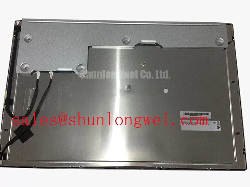
G240HVT01.0 AUO 24.0-Inch FHD AMVA3 LCD Display
Begin a replacement check by confirming the panel label, inspecting the frame for distortion, and comparing the original display interface before applying power. The AUO G240HVT01.0 is a 24.0-inch AMVA3 LCD display with a 1920(RGB) × 1080 FHD resolution, normally black transmissive operation, and an LVDS interface using two channels with 8-bit data. These points should be matched against the removed panel and the host display controller before installation.
| Parameter | Official Specification |
|---|---|
| Manufacturer | AUO |
| Model | G240HVT01.0 |
| Screen size | 24.0 inches |
| Resolution | 1920(RGB) × 1080, FHD |
| Display technology | AMVA3, normally black, transmissive |
| Luminance | 260 cd/m² typical |
| Contrast ratio | 5000:1 typical |
| Viewing angle | 89/89/89/89 degrees, left/right/up/down |
| Interface | LVDS, 2 channel, 8-bit |
| Backlight | WLED with LED driver |
| Backlight lifetime | 50,000 hours |
| Operating temperature | -20 to 70 °C |
The stated luminance and contrast values are typical specifications rather than universal readings for every operating condition. The actual result in a cabinet depends on the optical stack, cover window, ambient light, backlight drive, controller configuration, and thermal conditions. The panel specification does not establish a complete enclosure rating, vibration certification, or system-level EMC approval.
Preventing Frame Lag and Image Smearing in Sub-Zero Storage and Outdoor Industrial Facilities
For equipment exposed to sub-zero conditions, allow the display assembly to reach a stable temperature before judging image quality. Liquid crystal response can become slower as temperature falls, so moving graphics, scrolling alarms, and rapidly changing telemetry screens should be checked at the lowest intended operating condition rather than only on a warm service bench. The official operating range for this model is -20 to 70 °C; conditions beyond that range require separate system validation and should not be treated as an AUO specification.
A practical engineering check is to display dark, mid-tone, and high-contrast moving patterns while observing trailing, uneven transitions, or frame retention. These symptoms can also arise from controller timing, source-signal instability, or an unsuitable display profile. Verify the known-good controller and cable path before attributing the behavior to the panel. The supplied specifications do not state a gray-to-gray response time, so a precise response figure should not be assigned to this model.
Outdoor and heavy-equipment installations also need attention to the bezel interface. The specification supplied for G240HVT01.0 does not define an epoxy perimeter construction, sealing compound, or thermal-cycle qualification from -30 to 85 °C. Designers should therefore evaluate the complete bezel, gasket, cover lens, and cabinet sealing arrangement for condensation, dust ingress, and differential expansion. The aspect ratio and common display form-factor context can be reviewed through Display Aspect Ratio and Standard Screen Form Factors.
The WLED backlight is specified with a 50,000-hour lifetime and an LED driver. This figure should be interpreted within the manufacturer’s stated test conditions and the final system’s thermal environment. The controller or LED driver documentation should define any dimming method, PWM behavior, startup sequence, and brightness control limits. Do not assume a particular PWM frequency or duty-cycle linearity without verifying the driver documentation.
LVDS Timing, Pixel Clock, and Skew Compensation
G240HVT01.0 uses LVDS with two channels and 8-bit data. The source controller must therefore be checked for matching channel configuration, pixel format, timing tables, connector orientation, and data mapping. The available product information does not confirm a 20-pin or 30-pin connector, the logic supply voltage, power-on rise-time limits, JEIDA or VESA mapping, or individual pin assignments. The system integrator should verify the required supply voltage and connector definition from the original panel documentation before connecting the replacement.
During bench commissioning, inspect the display for split images, incorrect color order, intermittent lines, or a picture that remains offset after initialization. These conditions may indicate a mapping mismatch, cable seating problem, timing incompatibility, or signal-integrity issue. Compare the replacement against a known-good panel using the same controller and cable, then confirm the LVDS transmitter settings in the host equipment.
LVDS routing should preserve the differential relationship specified by the transmitter and receiver documentation. Keep paired conductors together, avoid unnecessary stubs, control the return path, and separate the display cable from high-current switching conductors where the cabinet layout permits. Any characteristic impedance target, skew limit, clock jitter margin, and data hold requirement must come from the applicable controller and panel interface documentation rather than being inferred from the screen size.
Power sequencing is also system-dependent. The panel should not be connected or disconnected while the equipment is energized, and the integrator should verify enable, reset, backlight, and image-data timing against the host controller’s service documentation. A compatible display image does not by itself prove that the long-term startup and shutdown sequence is suitable.
Flashlight Dark-Shadow Optical Diagnostic for Logic and Backlight Faults
When a field display appears dark, first record whether the image is completely absent or faintly visible. In a controlled bench test, apply a known-good video source and inspect solid red, green, blue, white, black, and gray screens. This primary-color sequence helps separate color-data errors, panel addressing problems, and illumination loss without assigning a single cause from one symptom.
A flashlight inspection can then be performed with the display powered under safe service conditions. Shine the light across the screen at an oblique angle and look for a faint image beneath the dark surface. A visible image may justify checking the WLED backlight path, LED-driver enable signal, connector seating, and thermal shutdown behavior. No visible image does not conclusively isolate the logic board, panel electronics, or video interface, so the result should be compared with voltage, enable, and signal measurements from a known-good assembly.
Vertical or horizontal line defects require a different approach. Photograph the pattern, note whether the defect follows the panel or the controller, and inspect the flexible connections without applying localized pressure to the glass. The product information does not provide a COG construction qualification or a field failure signature; claims about microscopic driver fractures should therefore remain diagnostic possibilities rather than confirmed causes.
Backlight brightness control must be evaluated through the installed LED driver. Confirm its supported dimming input, modulation method, startup behavior, and thermal limits from the driver documentation. Flicker, audible noise, or uneven brightness can originate in the driver, power supply, wiring, or controller configuration. The G240HVT01.0 specification confirms WLED operation with an LED driver but does not define a universal dimming frequency or duty-cycle response.
Industrial EMI Immunity, Chassis Shielding, and Common-Mode Suppression
In a cabinet containing variable-frequency motor drives, begin by separating display-image faults from power and grounding events. Monitor the LVDS path, panel supply, backlight enable, and chassis reference while the motor system changes operating state. Pixel jitter and horizontal noise bands may result from common-mode coupling, inadequate return paths, cable proximity, connector contact variation, or controller timing sensitivity.
A sound integration practice is to maintain a continuous, low-impedance shield termination appropriate to the equipment’s grounding architecture and to avoid leaving cable shields floating at unintended points. The exact termination method depends on the cabinet, cable construction, safety scheme, and EMC test plan. A common-mode ferrite may be evaluated when conducted interference is present, but its impedance behavior must be checked across the disturbance spectrum so that it does not compromise the LVDS eye or startup behavior.
Do not describe the panel itself as independently certified to CISPR, EN 55011, or another complete-equipment EMC standard. Compliance belongs to the assembled host system and its installation conditions. The G240HVT01.0 operating temperature range, LVDS interface, WLED backlight, and mechanical mounting arrangement should all be included in the system validation plan.
For preventive maintenance in a telematics display used in heavy mining shovel or earthmoving equipment, inspect the cabinet airflow path, gasket contact, cable strain relief, and connector retention during scheduled service. Maintenance Note: isolate power before inserting or removing the LVDS or backlight cable, and check the sealing gasket whenever the bezel is reopened. If a same-size, same-resolution replacement candidate is being assessed, engineers can review LMS700KF01-001 separately rather than assuming pin or timing compatibility. For related display-chain evaluation, LQ9D03B may be considered as a neutral reference for a peripheral display solution, while The Ultimate Guide to Industrial TFT LCD Technology provides broader background for interface and integration review.