Content last revised on September 27, 2026
GD200HFL120C8SNH Circuit Protection and Reliability: Voltage Headroom in the Installed System
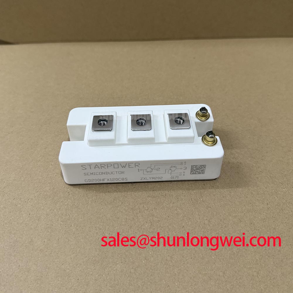
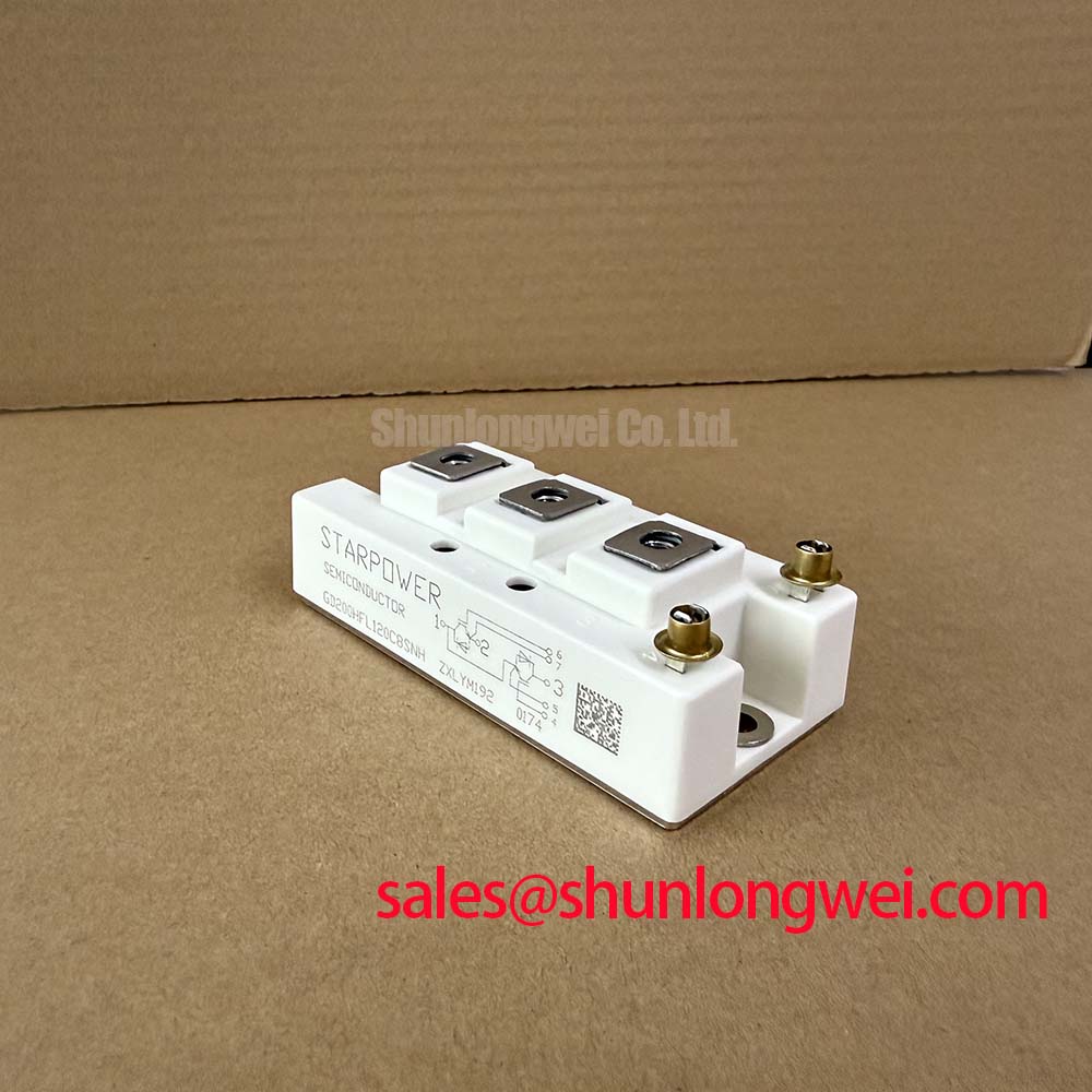
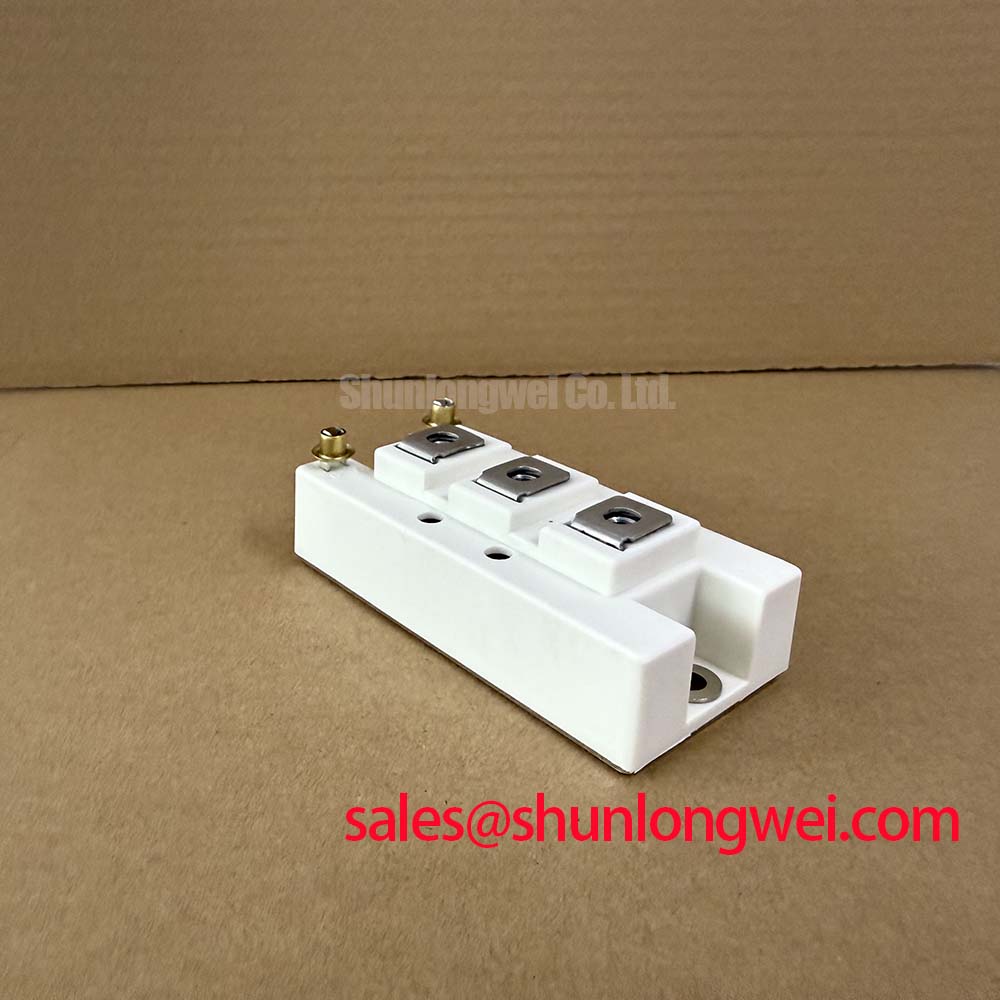
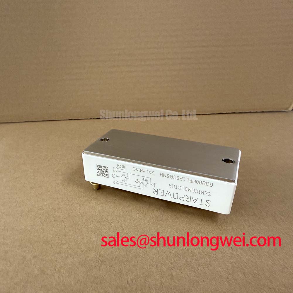
With the DC link isolated and discharged, compare the removed module’s terminal markings and mounting footprint with the equipment documentation before assessing GD200HFL120C8SNH as a replacement. StarPower identifies this device as a module rated at 1200 V and 200 A (Official Specifications). Those ratings establish an initial electrical screening boundary; they do not establish terminal compatibility, switching behavior, or suitability for a particular inverter.
The 1200 V rating is a device boundary, not an instruction to operate the DC link at that voltage. During a repair assessment, record the highest measured bus voltage during charging, regeneration, and switching, then compare the observed peaks with the applicable device limits in the original StarPower documentation. This is a Design Consideration: the system designer determines the working margin from the full operating envelope, including measurement uncertainty and protection response.
Altitude and atmospheric radiation can matter in some high-voltage semiconductor applications, but the supplied specifications do not establish a GD200HFL120C8SNH single-event burnout rate, failure-in-time figure, or altitude derating curve. No quantitative reliability prediction follows from the voltage rating alone. For equipment intended to operate at altitude, request application-specific evidence before assigning a reliability target; meanwhile, verify actual bus voltage and switching overshoot rather than treating a theoretical headroom calculation as a field measurement.
Inspect the installed insulation arrangement separately from the module’s semiconductor rating. A clean mounting surface, appropriate conductor spacing, and intact barriers support the assembly’s intended isolation scheme, but no clearance or dielectric-strength value can be assigned to this module from the supplied data. Dielectric strength and high-voltage breakdown testing explains the distinction between material breakdown behavior and an assembled product’s verified withstand performance. Likewise, SELV and PELV electrical safety concerns the design of the surrounding circuit; the module rating alone does not classify a control supply as safe extra-low voltage.
GD200HFL120C8SNH Operational Boundaries: Busbar Geometry and Switching Overshoot
Trace the DC-link capacitor, module power terminals, and return conductor as one switching-current loop before changing a failed assembly. As a Design Consideration, shortening that loop and arranging outgoing and return conductors close together can reduce stray inductance. Turn-off overshoot depends on both loop inductance and the rate of current change, so a satisfactory steady DC-link reading cannot establish the peak voltage seen at the module. Capture switching waveforms at the relevant operating conditions and evaluate the peak against the confirmed device limit.
Pro tip: Consider a symmetrical busbar layout to reduce turn-off overshoot, then verify the resulting voltage margin with switching tests on the assembled drive. Snubber capacitors, RC networks, and MOVs are system-level protection elements, not confirmed features of GD200HFL120C8SNH. If the original equipment uses them, check their connections and condition against its schematic. Their values and placement must be determined from measured transients and the equipment’s protection requirements; adding a larger component without testing can shift stress rather than resolve it.
For an inverter feeding a motor through a long cable, inspect the waveform at the motor as well as at the module when insulation stress is suspected. Cable reflections can raise the voltage at the motor terminals even when the module-terminal waveform appears acceptable. Filter selection belongs to the complete drive-and-cable design. Phase-angle conduction control and line-frequency ripple smoothing apply only where the documented converter topology calls for them; neither function should be inferred from this module’s 1200 V and 200 A ratings.
GD200HFL120C8SNH Thermal-Electrical Optimization: Gate Return and Mounting Checks
Compare the gate-drive schematic and terminal drawing with the installed wiring before assuming a separate Kelvin emitter connection exists. If the documented module provides an auxiliary emitter terminal, keeping its driver return separate from the main load-current path can reduce common-emitter feedback during switching. If it does not, do not assign an unmarked terminal that role. In either case, keep the gate loop compact and compare measured gate-to-emitter waveforms with those from a known-good channel when investigating oscillation or unintended turn-on.
The 200 A rating does not, by itself, define permissible current in every heatsink or duty cycle. Check the original thermal limits and mounting instructions, then inspect contact surfaces, thermal-interface coverage, and fastener seating during assembly. Press-pack hardware, disc springs, and double-sided cooling should only be used or adjusted where the documented module construction and equipment assembly require them; they cannot be assumed for a device identified only as a module.
For maintenance purchasing, P546A2005 can be included in a comparison of candidate repair parts, but its electrical ratings, topology, terminal assignment, dimensions, and thermal interface need independent confirmation before substitution. Electric material-handling and forklift traction inverters are possible evaluation contexts, not established applications or proof of fit for GD200HFL120C8SNH.
Assembly Integrity and Layout Architecture: Evaluating Negative Gate Bias and Miller Clamping
Examine both the driver’s commanded off state and the measured gate-to-emitter voltage during the opposite switch’s transition. Rapid voltage change can couple through an IGBT’s Miller capacitance; shared return impedance and ground bounce may add to the disturbance. Negative off-state bias and an active Miller clamp are alternative or complementary driver-design measures, but no bias level, clamp requirement, or integrated clamp feature is established by the supplied GD200HFL120C8SNH specifications. The driver designer should select and validate protection against the documented device limits and measured switching conditions.
Check commanded gate signals alongside the actual module-terminal waveforms when investigating suspected shoot-through. Dead time must account for the installed driver and switch behavior; a controller setting alone does not prove that one device has ceased conducting before the other turns on. The discussion in Evolution of Negative Off-Bias Gate Drive Circuits provides background for evaluating off-state gate control, while the repair decision still depends on the original circuit and bench measurements.
Bench warning: Isolate and discharge the DC link before touching module terminals or reconnecting gate-drive wiring. If a gate waveform differs from a known-good channel, inspect the driver supply, return path, connector seating, and probe reference before attributing the difference to the module. Verify the corrected assembly under controlled switching conditions, observing gate voltage and DC-link overshoot together.