

Content last revised on September 10, 2026
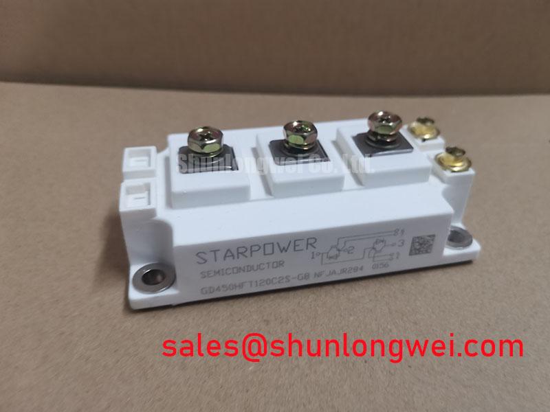
Transient Dynamics and Electrical Design for GD450HFT120C2S
In a high-speed rail or heavy freight locomotive traction inverter, the first electrical task is to preserve a symmetrical current path from the DC bus through the power terminals and back to the return bus. This is a design consideration, not an additional factory rating for the device. Busbars with unequal length, different overlap area, or uneven clamping can create different stray inductances. During turn-off, that imbalance can produce unequal voltage overshoot and current distribution even when the nominal circuit is symmetrical.
Use the removed assembly as a mechanical reference. Photograph the busbar stack, insulating films, support spacers, and gate cable routing. Inspect for discolouration, loose hardware, cracked insulation, carbon tracking, or metal particles near the power terminals. When the replacement is installed, keep the forward and return conductors physically close while maintaining the clearance and creepage distances required by the inverter insulation system. The correct spacing is system determined by working voltage, pollution level, altitude, insulation material, and the applicable railway or industrial safety requirements. It should be confirmed from the equipment design documentation rather than inferred from the part number.
Static current sharing can benefit from the positive temperature coefficient commonly associated with the saturation voltage of parallel IGBT paths, but the actual sharing performance remains dependent on matching, thermal coupling, gate-drive timing, busbar geometry, and operating point. The available product data supplied for this page confirms the voltage, current, and package values only; it does not establish a device-specific VCE(sat) curve or a guaranteed parallel-sharing condition. Designers should verify the relevant curve and test current balance at the intended switching frequency and load.
For field diagnosis, compare the suspect inverter with a known-good phase using the same meter range and test polarity. A cold impedance comparison can reveal an obvious short or an abnormal open path, but a meter result by itself cannot confirm dynamic switching health. If the static readings appear similar while the inverter still trips, inspect the gate driver supply, command waveform, desaturation circuit, current sensor path, and DC-link measurement. An oscilloscope with suitable differential and isolated probes should be used to compare gate-emitter voltage, collector-emitter behaviour, and phase current during a controlled low-energy test.
Before approving a direct replacement, engineers may also evaluate the neutral reference P546A2005, but any substitution requires a pinout, electrical rating, switching characteristic, thermal interface, and gate-driver compatibility review. Similar current and voltage labels do not prove interchangeability.
GD450HFT120C2S Protection and Baseplate Thermal Interface Control
Thermal work begins with the baseplate rather than the gate circuit. Remove all old interface material from the heatsink and module contact surfaces using a method approved for the equipment insulation and surface finish. Check the heatsink for burrs, embedded particles, local dents, and curvature. A distorted cooling surface can leave air pockets beneath the module, forcing local junction temperature upward even when the heat sink appears adequately sized.
A uniform thermal interface material layer is a design consideration. The supplied installation guideline calls for a controlled thermal grease layer in the 50 to 100 µm range, but the practical target depends on surface flatness, grease rheology, application tool, pressure distribution, and the manufacturer’s mounting instructions. The aim is to fill microscopic surface irregularities without creating a thick insulating film. Apply the material evenly across the effective contact area and inspect the spread pattern after a controlled trial fit. Voids, dry islands, and heavy ridges around the perimeter warrant correction before electrical commissioning.
Baseplate curvature compensation must be handled through the specified mounting method, not by forcing the module down with excessive tightening force. Use the correct fasteners, washers, spring elements, and sequence defined by the equipment or module documentation. Sequential tightening helps distribute pressure across the baseplate, while the final torque must follow the applicable fastener and module instructions. If a traction inverter uses disc springs or another calibrated pressure system, record their orientation and condition during removal. A flattened, cracked, or incorrectly stacked spring can change contact pressure and reduce cooling uniformity.
⚡ Field Alert: Disconnect the DC link and gate-driver supply before unplugging control connections, and follow the equipment manufacturer’s specified tightening sequence and torque rather than applying force by feel.
Double-sided cooling arrangements require additional care because the pressure path may include an upper heatsink, electrical insulation layer, thermal interface material, and mechanical frame. Designers should verify that both cooling faces remain parallel as the assembly is tightened. An uneven frame or unsupported busbar can load one side of the package while leaving the opposite side with incomplete thermal contact. After installation, check that the module is seated without rocking, that the power terminals are not carrying mechanical strain, and that the cooling plate remains aligned with neighbouring components.
Desaturation protection should be evaluated as part of the complete gate-drive system. A soft turn-off response can reduce the rate of current interruption during a detected short circuit, limiting the voltage stress caused by stray inductance. The suitable blanking interval, detection threshold, soft turn-off profile, gate resistance, and reset behaviour are system-determined. They must be verified against the actual driver, wiring inductance, DC-link voltage, and the short-circuit withstand information in the applicable StarPower documentation. Do not treat a generic desaturation timing value as an official specification of GD450HFT120C2S.
For high-side gate power, bootstrap capacitor selection must account for the driver’s gate-charge demand, quiescent current, leakage, charging interval, duty cycle, switching frequency, and allowable gate-voltage ripple. The required capacitance therefore cannot be calculated from the module’s 1200.0 V and 450.0 A ratings alone. Obtain the driver and gate-charge data, then confirm the capacitor voltage remains within the driver operating range during the complete high-side pulse sequence. Where the inverter uses isolated gate supplies instead of bootstrap power, the same verification should be applied to supply droop, isolation, turn-on sequencing, and fault shutdown.
PCB Gate Loop Layout Symmetry and Emitter Return Control
After the mechanical installation is stable, inspect the gate-driver board and cable harness. The gate loop should be treated as a high-speed power path, even though its current is much smaller than the main collector circuit. Keep the outgoing gate path and its return path close together, reduce unnecessary loop area, and avoid routing the gate return beside a high-current emitter or collector trace. The purpose is to reduce magnetic coupling and prevent the power current from modulating the gate reference.
If the module provides an auxiliary emitter or a dedicated control return, the system engineer should confirm its function from the original documentation before connecting it. The auxiliary return should be separated from the main high-current emitter path where the circuit topology permits. Sharing a narrow PCB copper section or a long harness segment can create emitter mutual coupling. That voltage disturbance may appear at the driver as an unwanted gate signal, especially during rapid current transitions.
Symmetry matters when multiple semiconductor paths are driven from a common control board. Match the physical route, connector contact condition, series components, and return reference for each channel. Do not assume that equal schematic lengths produce equal electrical lengths. Inspect solder joints, crimp terminals, board vias, cable shields, and connector locking features. A loose control connection can create intermittent switching behaviour that is difficult to reproduce during a low-voltage static test.
When a protection trip occurs without an obvious power-stage short, capture the gate-emitter waveform at the module terminals rather than only at the driver output. Compare the command waveform during turn-on, steady conduction, turn-off, and fault shutdown. Look for ringing, unexpected plateaus, unequal timing, or a gate disturbance that coincides with the phase-current transition. Use a known-good channel as the reference and change one variable at a time. The observation may indicate layout coupling, driver saturation, isolation-device behaviour, or a measurement-probe problem; it should not be assigned to the IGBT without correlating the complete waveform set.
Current feedback also deserves a physical review. A Rogowski coil can provide a useful fast-transient measurement principle for observing switching current, as described in the Rogowski coil reference. GMR and TMR technologies offer another approach for industrial current measurement, with their own bandwidth, offset, insulation, and placement considerations; background information is available in this GMR reference. These links describe sensing principles, not device-specific validation for GD450HFT120C2S. The final sensor choice and calibration remain part of the inverter design.
Benchtop Waveform Tuning and Common-Mode Transient Immunity
Conduct the first powered test with the inverter isolated from its full mechanical load and with a controlled DC-link source or an approved commissioning procedure. Confirm the gate-driver supply sequence, fault interlock, desaturation response, current feedback polarity, and emergency shutdown before increasing operating energy. The 1200.0 V rating of GD450HFT120C2S is an official product parameter, not permission to apply that voltage during an initial bench test. The test voltage, current, pulse width, and load must be defined by the system safety plan and the available switching data.
Common-mode transient immunity is primarily a gate-driver and isolation-system characteristic. The requested design target of more than 100 kV/µs should be treated as a system verification requirement, not as an official rating of this IGBT module. Likewise, a reinforced galvanic isolation barrier above 5 kV must be confirmed from the selected driver, isolator, transformer, insulation system, and test standard. Designers should verify isolation withstand, working voltage, creepage, clearance, dv/dt performance, and fault behaviour across the complete assembly.
During waveform tuning, place the differential probe reference at the actual module gate-emitter terminals and keep the probe loop as small as practical. Verify that the measurement setup itself is not introducing a false gate spike. Observe the gate signal while changing bus voltage and load conditions within the approved test envelope. A spurious pulse that appears only during a high-current commutation event may be associated with common-mode coupling, auxiliary-emitter reference movement, driver power-supply disturbance, or insufficient isolation-device immunity. Trace the timing relationship between the phase current, collector-emitter voltage, gate signal, and protection output before selecting a corrective action.
Soft turn-off during desaturation should be checked for controlled behaviour rather than simply rapid gate removal. The gate driver must discharge the gate in a way that limits fault current while avoiding an excessive collector-emitter overshoot. The correct profile depends on the module’s short-circuit data, driver output impedance, gate wiring, busbar inductance, DC-link voltage, and protection delay. Verify peak voltage and current on the oscilloscope against the permitted operating boundaries in the applicable technical documentation.
For traction inverter service, review the complete commutation path after every wiring change. A compatible mechanical footprint does not automatically confirm compatible gate charge, switching energy, short-circuit response, or thermal impedance. The related FZ3600R12HP4 may be assessed as a neutral reference for an associated rectifier or front-end stage, but it is not a substitute recommendation for the StarPower device. For broader test planning, the Power Electronics Masterclass provides additional system-level background.
Release the repaired inverter only after the gate signals remain symmetrical, protection operates through a controlled fault test, thermal contact has been verified, and the measured electrical stress remains inside the limits established by the original equipment design and applicable StarPower documentation. Record the final busbar arrangement, torque process, thermal interface method, gate-driver settings, waveform captures, and sensor calibration so that the next emergency repair can be compared with a known installation condition.