

Content last revised on September 29, 2026
CM600HU-12F Assembly Integrity and Gate Drive Layout
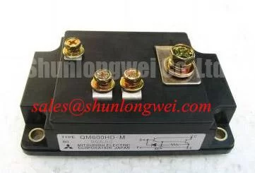
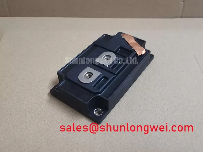
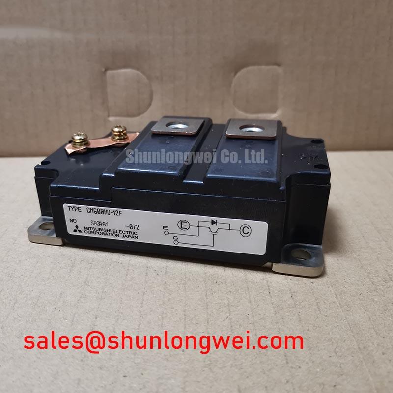
Start with the physical interface. Photograph the existing terminal connections before removal, then compare terminal markings, mounting points, contact surfaces and available enclosure clearance with the replacement and the equipment drawing. A matching current rating does not establish terminal compatibility. If the removed module shows heat discoloration or a loose power connection, inspect the mating busbar as well; changing the semiconductor alone will not correct a poor external contact.
For an inverter leg, rapid voltage change at a switching terminal can couple into the gate circuit of a device that is meant to remain off. Design Consideration: keep the gate drive return path compact and evaluate off-state gate control, including a driver-supported active Miller clamp if the measured switching behavior calls for one. Negative gate bias is a system-level option, not a specified requirement for this module in the supplied data. Its value, driver compatibility and allowable gate limits must be established from the original module documentation and the installed drive circuit.
During a controlled recommissioning test, observe the gate-to-emitter waveform at the relevant terminals rather than relying on a driver-board test point alone. An unexpected off-state rise warrants checks of the return connection, driver supply, nearby power-loop routing and the probe setup before assigning a cause. Field Alert: Isolate and discharge the DC link before moving a probe or disconnecting a gate lead.
CM600HU-12F Operational Boundaries and Pulsed Heating
The 600 A official current rating should be read alongside the manufacturer’s stated test conditions when the full datasheet is available. It does not, by itself, define an allowable overload pulse. For a stopped machine, retrieve the recorded current waveform, fault duration and cooling status before deciding whether the module was exposed to a thermal event outside its documented limits. An open circuit or short circuit found in a cold check can identify a failed electrical path, but it cannot quantify the preceding junction temperature.
Engineering Calculation: a pulsed-heating assessment combines loss during the measured event with the manufacturer’s transient junction-to-case thermal impedance over that event’s duration. A multi-RC model is useful only when its coefficients represent this device and its stated conditions. Without that data, reporting a peak junction temperature would imply precision the available specifications do not support. The equipment engineer should also account for case temperature and the complete path from module base to coolant or heat sink.
Remove old interface material and inspect both mating surfaces for damage before reassembly. Design Consideration: apply the selected thermal interface material according to its product instructions and verify mounting force against the module and fastener documentation; excess material or uneven contact can undermine the intended heat path. The behavior of grease and phase-change materials differs with installation and temperature, as outlined in this thermal interface material reference. Neither material choice nor an observed case temperature alone establishes a service-life prediction.
Short-circuit protection needs similar restraint. Confirm how the installed driver senses desaturation, blanks normal turn-on behavior and turns the device off after a fault. The supplied CM600HU-12F specifications do not establish a permissible detection delay or require a particular soft turn-off sequence. Those settings should be checked against the complete manufacturer documentation and measured on the actual drive assembly, not copied from another inverter.
CM600HU-12F Busbar Geometry and Protection Checks
Before energizing the repaired power stage, trace the DC-link connection through the busbar, module terminals and local capacitors. The relevant issue is the entire commutation loop: stray inductance in that loop contributes to collector voltage overshoot when current is interrupted. Design Consideration: keep opposing current paths close and connections mechanically consistent, then verify the measured turn-off peak against the module’s documented voltage limit under representative DC-link and load conditions. A target busbar inductance or snubber value cannot be prescribed from the two supplied ratings.
If a snubber or clamp is present, check its connection and condition against the equipment schematic. Inspect busbar insulation, spacing, support and fastener engagement after the module is seated; use the applicable equipment and insulation design documentation to judge clearance rather than treating a visual gap as proof of suitability. Where repeated faults have occurred, compare switching traces with a known-good phase using appropriately rated instrumentation. A higher observed peak may involve loop layout, clamp behavior, gate-drive timing or measurement placement, so verify each before changing components.
Procurement comparisons require the same discipline. The CM300DXDX1-24A is a separate model to assess, not a drop-in substitute established by its name. Compare its manufacturer-documented voltage and current ratings, circuit configuration, terminals, mounting pattern, drive requirements and thermal data with the original equipment requirements before considering a change. For broader selection and reliability questions beyond this product check, the Power Electronics Masterclass provides system-level context.
CM600HU-12F Switching Transients and Fault Turn-Off
When a drive trips on a switching fault, preserve the fault record before resetting it. Check whether the trip coincided with commanded turn-on, turn-off or an operating transition, then compare the gate command, measured collector behavior and driver fault output. Desaturation protection should distinguish a genuine loss of current control from normal switching behavior, while its fault turn-off must avoid creating an excessive inductive voltage peak. The timing and turn-off profile are decisions for the installed driver and verified module limits; they are not specified by the 600 V and 600 A ratings alone.
After replacing a failed module, inspect the associated driver channel and DC-link hardware before a controlled restart. Verify that the off-state command reaches the module terminals, the fault signal propagates to the controller and the measured switching peak remains within the manufacturer-documented boundary. If the equipment is a high-speed rail or heavy freight locomotive traction inverter, treat that as a potential compatibility review only: its operating voltage, qualification requirements, mechanical interface and protection design must independently support use of the CM600HU-12F.