Content last revised on September 11, 2026
KCG057QVLDG-G00 Inspection and Specifications
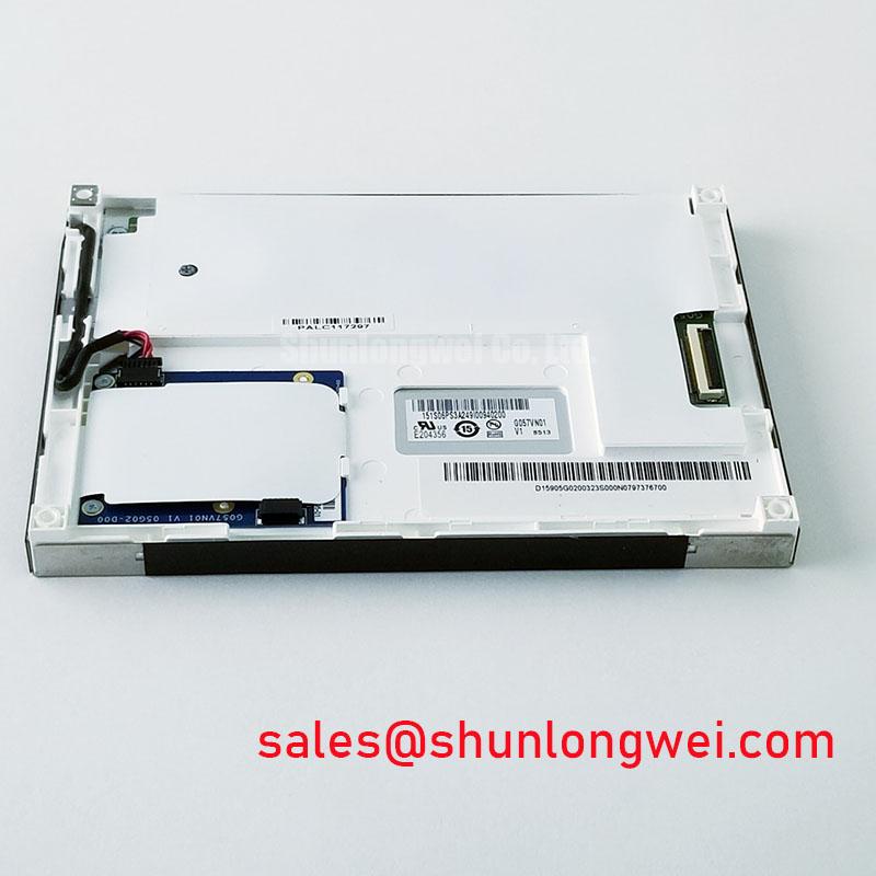
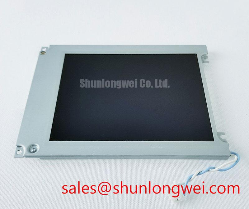
With power removed, inspect the connector area of the KCG057QVLDG-G00 for bent contacts, uneven cable insertion, surface contamination, and stress marks before applying a full-screen test pattern. This Kyocera LCD module has a 5.7 inch active display class, 320(RGB)×240 QVGA resolution, CSTN LCD technology, and an 8 bit parallel data interface. Its official display configuration is Normally Black and transmissive, with a WLED edge-light backlight.
For incoming inspection, display solid black, white, red, green, and blue fields before judging a machine fault as a panel failure. Uniform fields make isolated bright pixels, dark pixels, color nonuniformity, or backlight edge variation easier to observe than a normal application screen. The module is officially specified at 350 cd/m² typical luminance, which is relevant when comparing replacement-screen visibility in brightly lit control cabinets, laboratory terminals, and service equipment.
| Official Specification | KCG057QVLDG-G00 Value |
|---|---|
| Manufacturer | Kyocera |
| Screen Size | 5.7 inches |
| Resolution | 320(RGB)×240 QVGA |
| Display Technology | CSTN LCD, Normally Black, Transmissive |
| Luminance | 350 cd/m² typical |
| Backlight | WLED, edge light type |
| Backlight Lifetime | 50,000 hours typical |
| Signal Interface | Parallel Data, 8 bit |
| Operating Temperature | 0°C to 60°C |
| Storage Temperature | −20°C to 60°C |
WLED Backlight Verification and Parallel Data Timing Boundaries
The KCG057QVLDG-G00 uses an officially specified WLED edge-light backlight. It is therefore inappropriate to apply CCFL striking-voltage assumptions to this module. A service technician investigating a dark screen should first separate the observation into two questions: whether the parallel-data image is present and whether the WLED backlight is operating. Viewing the panel under controlled ambient light can help identify whether faint image content exists before the host system, panel cable, or illumination path is disturbed.
The official specification identifies an 8 bit parallel data interface. It does not establish LVDS signaling, TTL clock tolerance, transmitter jitter limits, PWM dimming range, or driver current requirements in the provided product data. Those items must be verified from the original host hardware documentation and the applicable detailed panel documentation before an interface board, cable assembly, or replacement display is approved.
Design Consideration: parallel display buses depend on stable data relationships, control signals, grounding continuity, and cable seating. If the image has intermittent color errors, missing bands, unstable content, or an apparently shifted image, inspect the cable alignment and connector retention before assuming an LCD-cell defect. Compare the data path with a known-good signal path using suitable test equipment where available, rather than assigning one symptom to one cause.
💡 Bench Tip: Use ESD precautions and insert the display cable squarely and evenly before engaging its retention feature, because an angled connection can create misleading image or backlight symptoms.
The stated backlight lifetime is 50,000 hours typical, which is an official specification for the WLED backlight system. This value should not be converted into a guaranteed installed service life, because operating time depends on the host duty cycle, thermal conditions, electrical drive implementation, enclosure design, and maintenance environment.
Dark Field Inspection and Mechanical Mounting Control
Set the display to a black field after warm-up, then observe the screen from normal viewing distance and from shallow angles. This practical check is useful for identifying visible light nonuniformity, localized pressure effects, isolated bright points, and edge-related brightness differences. Since the KCG057QVLDG-G00 is specified as a Normally Black transmissive CSTN LCD, the dark-field inspection should be performed with the complete host display assembly powered in its intended configuration.
The supplied official data does not define bezel compression limits, fastening torque, a light-guide compression threshold, panel thickness, mounting-hole dimensions, or a required chassis opening. These mechanical values must not be inferred from the screen size alone. Engineering Recommendation: retain the original mounting arrangement where possible, avoid concentrating force at any display edge, and verify that a replacement assembly is not being flexed by the enclosure, cable routing, touch overlay, or front bezel.
Where a display develops an optical irregularity after reassembly, release power, inspect the mounting stack, and repeat the full-screen pattern test before changing electronic parts. A visible change after enclosure adjustment may indicate mechanical interaction, but it does not by itself establish the precise origin of the effect. The system integrator should verify the original panel documentation for the permitted mounting method and dimensions.
Engineers assessing another panel for a legacy service situation can review the KCG047QV1AA-G210 as a separate display option. It should not be treated as a direct electrical or mechanical substitute without checking its interface, active area, mounting arrangement, optical performance, and host firmware compatibility against the original system requirements.
Operating Temperature Limits and Image Response Assessment
The official operating range for the KCG057QVLDG-G00 is 0°C to 60°C. Its official storage range is −20°C to 60°C. Storage temperature and powered operating temperature are different conditions, so a unit kept at a low storage temperature should not be considered qualified for energized use below 0°C. The provided specifications do not support claims of operation at −30°C or +85°C.
Design Consideration: liquid-crystal displays can exhibit slower visual transitions as temperature falls. If an image appears to update differently during a cold start, allow the display and the surrounding equipment to stabilize within the specified operating environment, then compare behavior using the same test pattern and host signal source. This controlled method avoids confusing thermal behavior with a data-interface fault or a backlight issue.
The original equipment documentation should determine whether a heater, fan, sealing arrangement, or other environmental control is present. No such system feature is specified for the KCG057QVLDG-G00 itself. Similarly, no PWM frequency, dimming duty-cycle characteristic, response-time value, or acoustic performance limit is included in the provided official parameters. When integrating the module into a diagnostic or surgical display terminal, designers should validate visual stability, dimming behavior, and image-update performance within the complete equipment configuration.
For a broader engineering reference on industrial screen selection, installation conditions, and HMI reliability planning, see Industrial Display & HMI Solutions. That resource can support system-level evaluation, while the KCG057QVLDG-G00 must remain assessed against its own stated environmental and interface specifications.
Thermal Uniformity Checks for Long-Term Optical Stability
During a powered inspection, compare the center and perimeter appearance of white, gray, and black patterns after the assembly has reached normal operating condition. This can reveal whether the visible presentation changes with enclosure heat, local airflow, cable placement, or front-bezel contact. The KCG057QVLDG-G00 has a WLED edge-light configuration, and its 350 cd/m² typical luminance provides a defined starting point for optical comparison when the same test conditions are used.
The official product parameters do not specify internal optical materials, heat-spreader geometry, LED junction temperature, L70 or B50 metrics, color-shift limits, thermal resistance, or permitted external rail design. It is therefore not appropriate to state a mandatory heat-spreader size or to predict a color-change mechanism for this exact module. Design Consideration: avoid placing external heat sources directly against the display perimeter, and evaluate enclosure ventilation where sustained temperature rise could affect display appearance.
A gradual brightness or color difference can arise from several interacting factors, including the host backlight supply, operating duration, ambient conditions, optics within the full assembly, and display settings. Use repeatable screen patterns, the same viewing angle, and a stable host configuration during comparison. If quantitative luminance or chromaticity verification is required, measure it with calibrated optical equipment under the equipment maker’s approved test conditions.
For high-precision surgical navigation and ultrasound diagnostic display terminals, the practical integration check is not a generic medical claim for the panel. It is confirmation that the original terminal’s electrical interface, enclosure mechanics, environmental range, visual acceptance criteria, and applicable equipment-level compliance requirements remain satisfied after service. The module’s known boundaries are its 5.7 inch QVGA format, 8 bit parallel data interface, WLED edge-light backlight, and specified 0°C to 60°C operating range.