

Content last revised on November 5, 2026
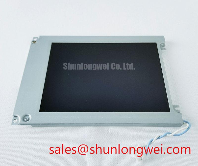
KCS057QV1AJ-G39 Replacement and Compatibility Checks
- Confirm the installed panel marking and compare it with KCS057QV1AJ-G39 before removing the original display.
- Record the existing panel connector orientation, cable routing, controller interface, and backlight arrangement.
- Inspect the bezel opening, mounting points, flex cable clearance, and rear-panel pressure points before mechanical installation.
- Isolate the display supply and backlight circuit before disconnecting the flat cable or high-voltage illumination wiring.
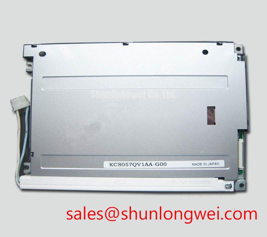
KCS057QV1AJ-G39 is a Kyocera TFT active-matrix LCD panel. The first replacement task is an interface and mechanical comparison rather than a simple visual check: the system integrator should match the original controller, connector definition, display timing, power requirements, illumination circuit, and mounting envelope against the original panel documentation.
| Parameter | Documented Specification |
|---|---|
| Model | KCS057QV1AJ-G39 |
| Manufacturer | Kyocera |
| Product category | TFT active-matrix LCD panel |
| Interface and electrical ratings | Consult the panel datasheet and the original equipment interface documentation before energizing |
For equipment such as an automated guided vehicle or forklift telematics console, physical compatibility includes more than the visible image area. The replacement must sit squarely in the bezel, retain even support across the panel perimeter, and leave the flex connection free from bending or compression. A panel that fits the opening but changes the cable exit direction or connector engagement depth can create intermittent faults during vehicle vibration and service access.
Kyocera’s industrial display information provides useful background for evaluating display technologies and optical integration. For broader service work involving industrial HMI assemblies, the Industrial Display & HMI Solutions reference can be used alongside the equipment manufacturer’s service documentation.
CCFL Resonant Inverter Striking Potential and Ignition Arc Fault Prevention
When the original terminal uses a cold-cathode fluorescent backlight, the inverter and lamp circuit must be treated as a separate compatibility boundary from the LCD panel itself. The product identification establishes that this is a TFT active-matrix panel, but it does not establish a particular inverter voltage, lamp current, striking waveform, or ballast transformer design. Those values must come from the original panel and inverter documentation rather than from the display type alone.
During service, inspect the lamp harness for carbon tracking, damaged insulation, loose crimp terminals, and signs of corona near the transformer and lamp connector. High-voltage striking energy can find a shorter path through contaminated surfaces, compressed insulation, or an incorrectly positioned cable. The practical objective is to preserve the original creepage and clearance arrangement, keep the high-voltage path away from conductive brackets, and prevent the harness from rubbing against the enclosure during vehicle movement.
A resonant inverter should be evaluated with the correct lamp load connected. Starting the inverter with an open or substituted load can alter the resonant condition and produce abnormal stress. Check the lamp current regulation, ignition behavior, and steady illumination with suitable high-voltage measurement equipment and the equipment maker’s specified limits. A current waveform that changes sharply during ignition, or a lamp that repeatedly attempts to strike, calls for inspection of the lamp, transformer, connector, and insulation path before the LCD panel is condemned.
Arc prevention is also an enclosure issue. Dust, cleaning residue, moisture, and sharp metal edges can reduce the practical isolation margin around the lamp circuit. The replacement panel should retain the original insulating barriers and cable clamps. Do not substitute an LED backlight driver or CCFL inverter based only on connector similarity; the illumination technology, electrical load, dimming method, and fault response must agree with the controller assembly.
Kyocera’s display technology reference is useful when comparing industrial optical and display-system considerations: Kyocera Industrial TFT-LCD Display Technologies. It should be read as technology background, while the exact KCS057QV1AJ-G39 interface remains governed by the applicable panel documentation.
Cold-Start Response and Optical Stability in Sub-Zero Equipment
Cold operation can slow liquid-crystal response as the liquid-crystal material becomes more viscous. On an AGV or forklift display, this may appear as slower image transitions, temporary contrast changes, or image persistence after power-up. These observations should be compared with a known-good unit under the same enclosure temperature and illumination conditions before changing the controller or panel drive circuitry.
Optical performance depends on the complete display assembly and viewing conditions. Strong ambient light, surface contamination, scratches, pressure marks, and incorrect cover-lens spacing can affect readability. Preserve the original optical layers and their orientation during installation. A replacement cover window with a different optical stack can produce glare or a washed-out image even when the electrical interface is correct.
For panels exposed to sunlight, inspect the viewing surface for haze, bubbling, delamination, discoloration, and localized contrast loss. These symptoms can arise from optical-layer aging, adhesive stress, thermal cycling, or enclosure conditions. They should not be attributed to the LCD panel without comparing the cover layer and illumination path.
Cold-start evaluation should include the complete display assembly rather than the bare LCD panel. Record the time from system power application to stable readable characters, then compare the result with the original unit while monitoring the enclosure temperature. Check whether the controller is applying the intended power sequence and whether the backlight reaches stable operation. When the display is installed behind a sealed bezel, designers should also assess heat accumulation during continuous operation because local temperature gradients can affect optical uniformity.
Pro Tip: Keep the panel face supported evenly during bezel installation; localized pressure can create visible optical non-uniformity even when the electronics are operating correctly.
LCD Drive and Image Stability Across Industrial Temperatures
Image quality depends on the relationship between the controller’s drive signals, the panel power rails, and the temperature-dependent liquid-crystal response. A contrast change across temperature therefore calls for coordinated inspection of the panel power supply, controller timing, and optical condition. The KCS057QV1AJ-G39 is a TFT active-matrix panel, but its required supply voltages and temperature compensation method must be taken from the matching panel documentation.
Use an oscilloscope at the controller-side test points to observe supply ripple, startup order, and waveform stability under the actual cable load. Excessive ripple can produce image instability, while an incorrect startup sequence can expose the panel to unintended operating conditions. The preferred diagnostic comparison is between the suspect assembly and a known-good assembly using the same probe reference and ground arrangement.
The controller interface may use parallel display signals such as frame, line, and dot-clock functions, but the signal names and electrical levels must be confirmed from the original controller documentation. Do not infer a four-bit or eight-bit bus assignment from connector position alone. Verify data-bit order, clock polarity, latch timing, frame synchronization, and enable behavior before changing firmware or rewiring the harness.
Power sequencing deserves attention during replacement. The system integrator should verify that the logic supply, panel power rails, and display data activity appear in the required order for the installed controller. A rail that rises late, collapses during backlight startup, or remains active after logic power removal can create symptoms that resemble a defective LCD panel. Capture the supply and control signals during a complete cold start and controlled shutdown, then compare them with the equipment service limits.
High-frequency servo drives and vehicle power electronics can also couple noise into the display harness. Route the display cable according to the original equipment layout, maintain the intended return path, and separate sensitive timing lines from switching nodes where the enclosure permits. EMC behavior belongs to the complete machine assembly; the LCD panel itself should not be represented as independently certified for a system-level CISPR or EN 55011 result.
Data Setup and Hold-Time Margin on Flat Ribbon Cables
Flat ribbon connections require attention to contact alignment, cable orientation, insertion depth, and strain relief before timing analysis begins. A connector that is partially engaged can create missing image areas or unstable display behavior that varies when the vehicle enclosure is moved. Inspect the contacts under suitable lighting, confirm the locking mechanism, and ensure that the cable is not folded directly at the connector exit.
For a parallel display interface, the controller’s data must remain stable around the active edge of the pixel clock, while line and frame signals must retain their intended relationship to the data stream. The relevant setup and hold margin is determined by the controller, cable capacitance, connector loading, signal edge rate, and panel input requirements. Verify the actual waveform at the panel-side connector rather than relying only on the controller output test point.
Long or tightly folded ribbon cables can increase capacitive loading and introduce ringing, skew, or edge distortion. Keep the cable geometry consistent with the original installation and avoid placing it across inverter wiring or high-current motor conductors. When a display fault changes with cable position, compare the clock and synchronization waveforms while gently reproducing the service position; this can reveal a connection or signal-integrity issue without assuming that the LCD panel has failed.
Power-up timing should be checked with the data bus included in the measurement. The controller should not begin sending uncontrolled display activity while the panel power supplies are still establishing their operating state. Designers should verify the complete sequence under normal startup, brownout recovery, emergency stop, and rapid power cycling conditions, with the final limits determined by the controller and panel documentation.
For AGV and forklift telematics installations, the final compatibility review should cover the standard-form-factor mechanics, connector and cable geometry, TFT optical behavior, backlight technology, power requirements, and controller timing as one assembly. This approach keeps the replacement assessment tied to the documented identity of KCS057QV1AJ-G39 while leaving system-specific electrical limits to the equipment design records.