Content last revised on September 27, 2026
Benchtop Waveform Tuning: AC Input Transient Overvoltage Clamping on KT224515
With the equipment isolated and stored energy safely discharged, compare the KT224515 marking, terminal arrangement, and cold-state measurements with the machine schematic before reconnecting the power circuit. Record measurements with the module disconnected from parallel paths wherever the service procedure permits; surrounding snubbers and control circuits can otherwise obscure the result. A meter check is a preliminary screen, not proof of blocking capability or acceptable operation under load.
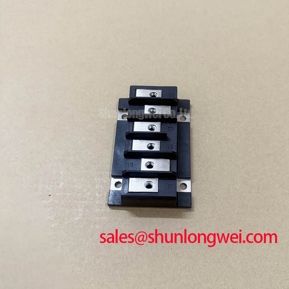
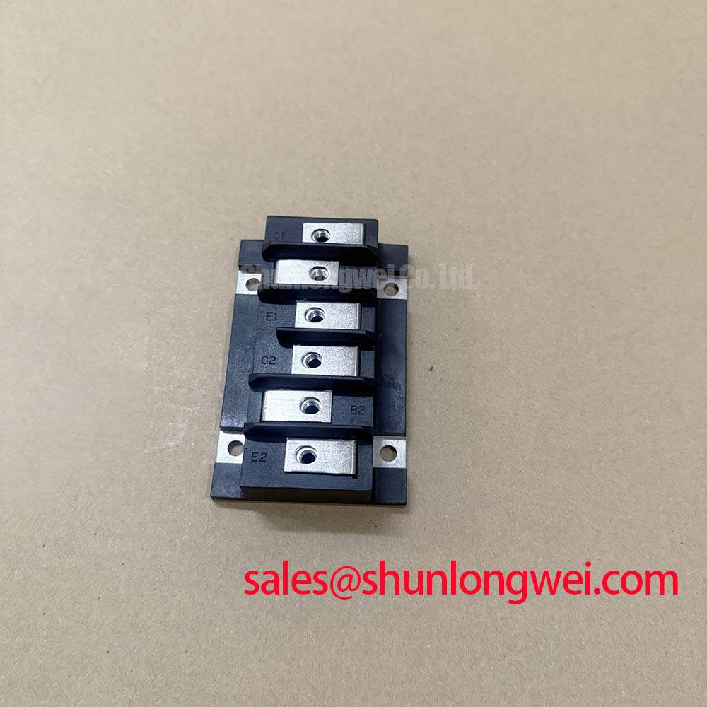
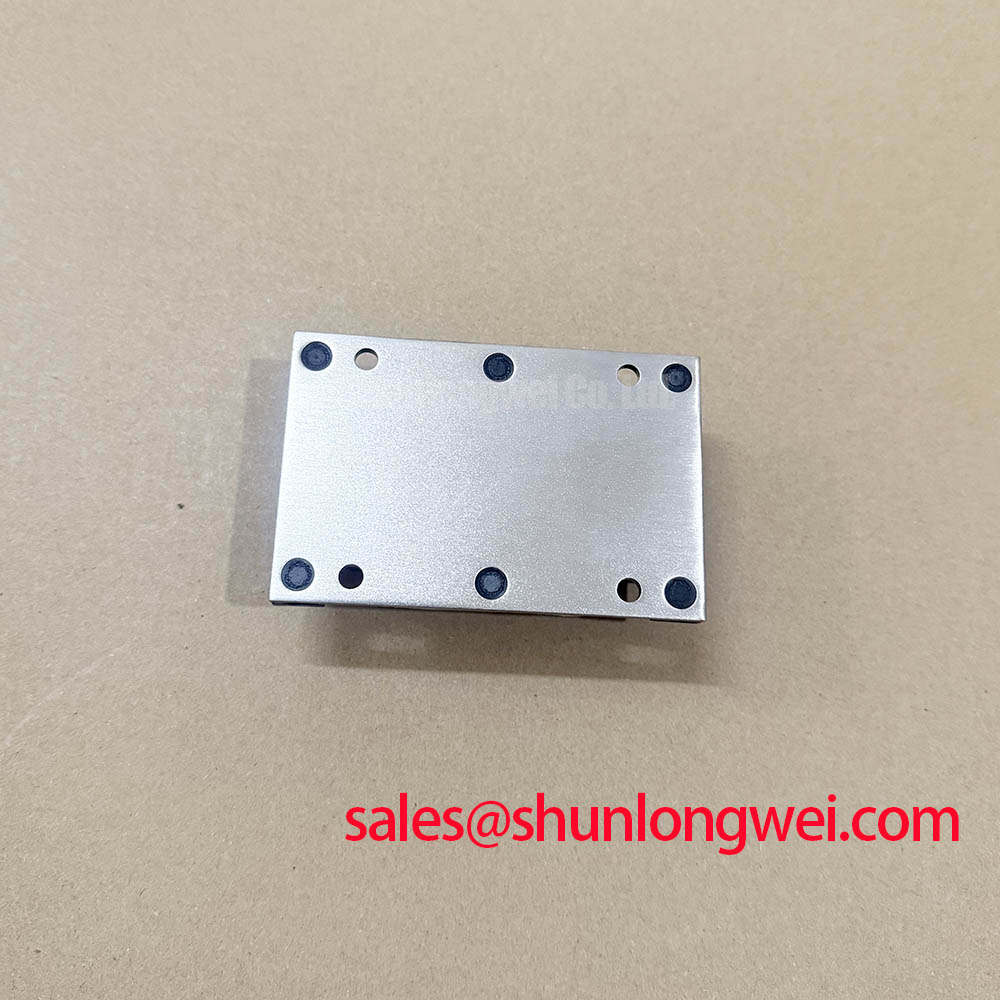
The Powerex KT224515 is identified here as a thyristor power module with a 600.0 V voltage rating, a 150.0 A current rating, and a POW-R-BLOK package. These supplied official specifications establish the initial selection boundary, but they do not establish terminal assignments, surge capability, cooling requirements, or gate-drive settings.
| Product attribute | Official Specification | Integration boundary |
|---|---|---|
| Model | KT224515 | Match the complete identification to the equipment parts documentation. |
| Manufacturer | Powerex | Use the applicable manufacturer documentation for electrical and mechanical details. |
| Voltage rating | 600.0 V | Confirm the blocking parameter definition and its operating conditions before approval. |
| Current rating | 150.0 A | Confirm the waveform, temperature, and cooling conditions associated with the rating. |
| Package | POW-R-BLOK | Verify the outline, mounting arrangement, and terminal geometry. |
The 600.0 V device rating must not be treated as an allowable AC supply voltage. For a three-phase motor solid-state soft starter, designers should verify the actual voltage imposed across each semiconductor during blocking, switching disturbances, and the equipment’s specified abnormal conditions. Describing the equipment as high voltage does not establish compatibility with this module; the circuit topology and measured electrical stress remain decisive.
As a Design Consideration, MOV selection depends on continuous applied voltage, transient exposure, clamping behavior, and coordination with upstream protection. RC snubber selection depends on the circuit’s voltage transition behavior, component dissipation, and layout. The explanation in Snubber Circuit Networks for Transient Voltage Clamping provides general circuit context, not KT224515 component values. Final choices should be validated against the equipment specification and measured waveforms.
Where surge-immunity testing applies, the relevant standard designation is IEC 61000-4-5, not “IEEE 61000-4-5.” Its applicability and test conditions belong to the equipment assessment; no module-level compliance claim follows from the voltage rating. Consult Powerex High Power Semiconductor Modules for manufacturer documentation before assigning blocking limits, terminal functions, or protection settings.
KT224515 Thermal-Electrical Optimization: Evaluating Post-Surge Reverse Voltage Blocking
After an overcurrent event, retain the failed fuse identification and review the protection record before installing another module. As an Engineering Recommendation, compare the fuse manufacturer’s clearing characteristics with the applicable semiconductor withstand data under compatible test conditions. A fuse selected only by nominal current does not establish semiconductor protection, and the module’s 150.0 A rating is not a substitute for surge-current or energy-withstand information.
The available official specifications do not establish a nonrepetitive surge-current rating, a half-cycle test duration, an I²t limit, or post-surge reverse-voltage conditions. Consequently, no numerical fuse-coordination table or allowable surge waveform can be assigned here. Obtain those values from the exact KT224515 documentation, including initial temperature, waveform shape, and any restrictions on subsequent voltage application. Similar package markings are insufficient grounds for borrowing another device’s limits.
As a Design Consideration, surge heating can reduce the available thermal margin before blocking voltage is reapplied. Assessment therefore needs the actual current event, the initial thermal state, and the manufacturer’s applicable transient limits. If the event was not captured, a later cold-state measurement cannot reconstruct its peak junction temperature. Record that limitation rather than translating a satisfactory meter reading into a serviceability guarantee.
During recommissioning, qualified personnel should capture current and voltage using equipment appropriate to the circuit potential and the machine’s approved service procedure. Compare phase behavior under equivalent operating conditions and investigate differences alongside trigger timing, connections, and load balance. Reverse-voltage testing should follow an authorized procedure; an improvised high-voltage bench test can exceed an undocumented terminal or insulation boundary without producing a useful acceptance result.
Field Diagnostics and Commissioning: Uniform Heatsink Contact Pressure in KT224515 Topologies
Remove old interface material using a method compatible with the module and heatsink surfaces, then inspect the mounting plane for debris, raised damage, and evidence of uneven seating. The POW-R-BLOK designation alone does not establish baseplate composition, mounting dimensions, screw size, or permissible clamping load. Confirm those details from the package drawing before deciding whether the existing hardware and heatsink are suitable.
As a Design Consideration, uniform seating helps maintain a consistent thermal interface without imposing unnecessary mechanical stress on the package. Follow the manufacturer’s fastening sequence, torque specification, and interface-material instructions where available. Do not import torque or paste-thickness values from a different module merely because its mounting hardware looks similar. Mounting fasteners and electrical terminals can also have different tightening requirements.
Field Alert: Do not tighten mounting or terminal hardware to a generic torque value; use the documented requirement for the exact module and connection.
No verified junction-to-case thermal resistance or maximum junction temperature is established by the supplied specifications. Thermal approval therefore requires the exact thermal data together with the equipment’s conduction duty, cooling arrangement, and environmental conditions. As an Engineering Recommendation, record heatsink temperature at consistent locations during controlled commissioning, but do not present that measurement as junction temperature without a validated thermal assessment.
When a machine also has an operator-display fault, keep display diagnostics separate from power-stage approval. An HMI alarm or blank screen does not independently establish KT224515 failure. For that separate subsystem, The Ultimate Guide to Industrial TFT LCD Technology provides context for display selection and interface checks; it does not supply semiconductor mounting or protection specifications.
Benchtop Waveform Tuning: Gate Trigger Current and Temperature Dependence on KT224515
Verify the terminal map before attaching a gate-drive probe or reconnecting control wiring. Do not infer gate and cathode positions from another POW-R-BLOK product. The supplied ratings do not establish gate trigger current, trigger voltage, maximum gate power, latching current, or holding current. Those limits and their temperature conditions are required before approving an existing trigger board for this module.
As a Design Consideration, evaluate the trigger waveform at the device connection rather than relying solely on the controller output. Wiring impedance and the return path can change the delivered pulse. Check pulse polarity, amplitude, duration, and timing against the applicable manufacturer limits across the intended operating conditions. Gate-current rise time must be selected from documented requirements and system validation, not imposed as an unsupported numerical threshold.
For soft-starter compatibility assessment, designers should verify that the firing sequence supports the actual load-current waveform and the device’s documented latching requirements. Repeated firing pulses are a controller strategy to assess, not an inherent KT224515 requirement. Gate pulse shaping also cannot replace verification of main-current turn-on limits. If triggering is inconsistent, compare the delivered waveform with a known-good channel while checking supply behavior, connections, and phase timing.
Complete the repair record with the confirmed terminal assignment, protection-component references, fastening requirements, and observed trigger waveforms. Release the installation only through the equipment’s approved commissioning process, with unresolved limits referred to the responsible system engineer. This keeps the acceptance decision tied to the KT224515’s documented boundaries rather than assumptions about interchangeable power modules.