

Content last revised on September 11, 2026
Logic Supply Voltage Sequencing and Driver IC Latch Up Risk Control
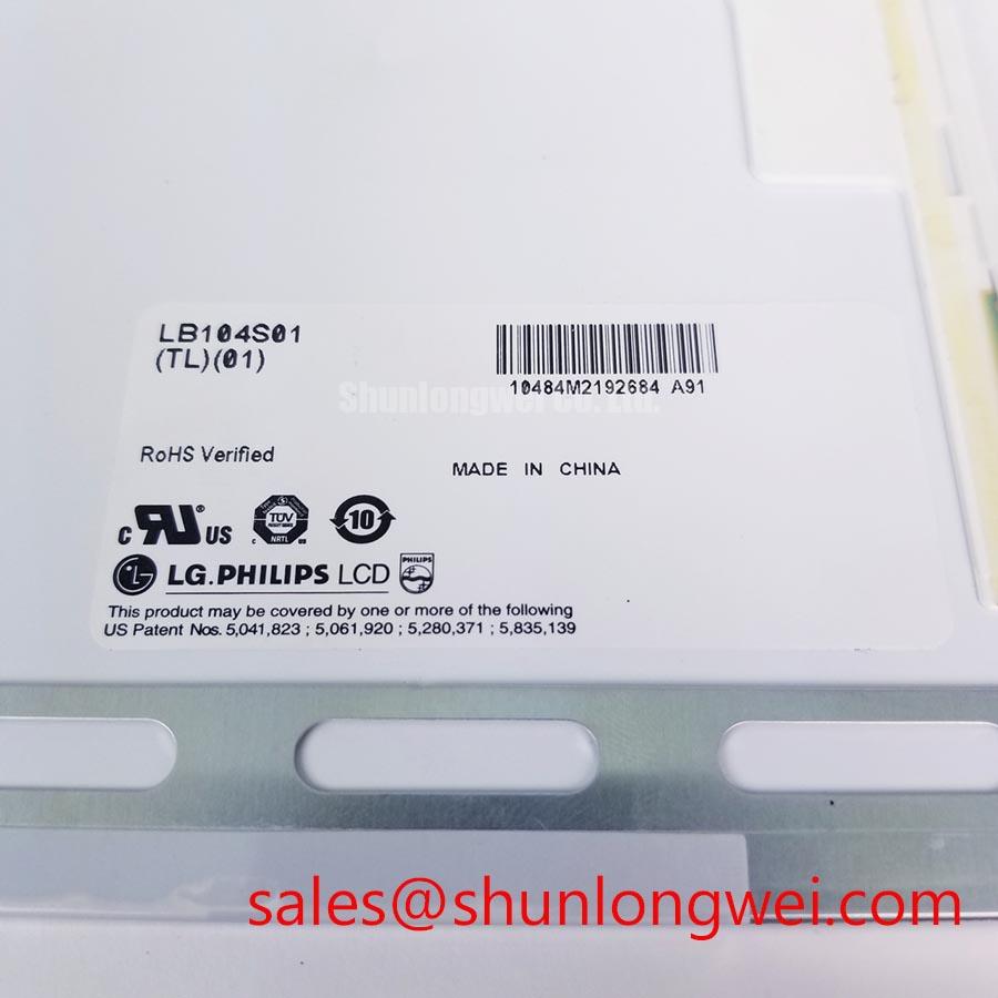
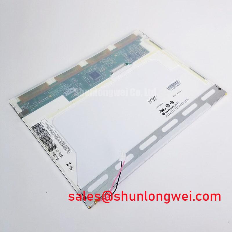
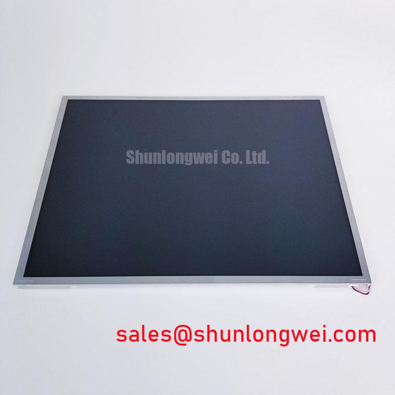
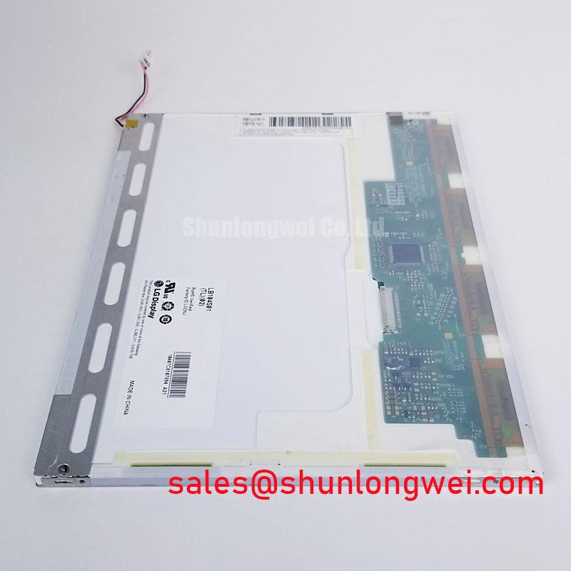
With power removed, inspect the LB104S01-TL04 module perimeter, connector area, mounting points, and display surface before reconnecting it to the original HMI assembly. This unit is identified as an Industrial Grade LCD/HMI Panel from LG Display, supplied as a TFT LCD Display Module. Any supply rail, interface mapping, backlight input, timing, optical, and mechanical requirements must be confirmed against the original panel documentation and host equipment documentation before installation.
Before fitting the LB104S01-TL04 into an industrial display controller, compare the original panel label, controller schematic, cable assembly, and panel documentation as one set. A replacement display can have the correct mechanical outline while still requiring a different logic supply arrangement, data mapping, or power sequence. The system integrator should verify the required logic supply voltage from the original panel documentation rather than assuming a rail value from another display family.
Power sequencing is a Design Consideration because an LCD module is part of a complete display assembly that includes a host controller, signal cable, power source, and backlight control path. The relevant commissioning check is whether the host powers the panel logic, video data, enable signals, and illumination circuitry in the order required by the original equipment. An incorrect sequence can produce an inactive image, unstable start up behavior, intermittent lines, or image corruption without proving that the display itself has failed.
Inspect the original interface designation before reconnecting any cable. In particular, verify whether the host controller uses a differential display interface and whether its data mapping matches the intended panel configuration. A split image, incorrect color ordering, repeated columns, or unstable synchronization can arise from interface mapping differences, cable damage, controller configuration, or power sequence behavior. These observations should be checked with the known good signal path where available, rather than attributed to one cause.
For industrial cabinet work, controlled cable routing is an Engineering Recommendation. Keep display signal conductors separated from high energy switching paths where practical, preserve the original cable grounding arrangement, and avoid pinching the flexible cable beneath enclosure hardware. When evaluating a panel for a telematics display in heavy earthmoving equipment, the equipment team should also verify enclosure sealing, vibration retention, controller compatibility, and daylight readability under the actual operating conditions.
Guidance on controlled electrical and test practices can be reviewed through the JEDEC Solid State Technology Association Standards. Those resources support general engineering assessment, but they do not replace the host system documentation for this specific LG Display module.
Flashlight Dark Shadow Optical Diagnostic to Isolate Logic and Backlight Failure Modes
Begin a bench check by applying the host system’s approved operating conditions, then display controlled red, green, blue, white, and dark image patterns from a known stable source. Observe whether defects remain fixed to the same physical display area, change with input content, appear only after warm up, or respond when the cable is carefully secured. This method gives repair personnel useful evidence without assuming that any single visible symptom identifies one failed part.
A flashlight dark shadow inspection can assist when the screen appears black or extremely dim. With the assembly operating under approved service conditions, direct a low intensity flashlight across the surface at an oblique angle and look for a faint changing image. A faint image may indicate that the image generation path is active while the illumination path or its control conditions require further investigation. No faint image does not independently confirm a panel fault, because host video, panel supply, enable control, cable continuity, and display controller state should also be verified.
Do not use excessive pressure on the active area while inspecting localized lines, shadows, or nonuniform regions. Mechanical stress at the bezel, mounting frame, or cable transition can alter a symptom temporarily and obscure the original condition. Inspection should instead include the connector lock, cable folds, enclosure contact points, and the condition of any gasket that supports the module. Surface irregularities can also be caused by enclosure loading or uneven fastener pressure rather than an optical defect intrinsic to the display.
⚠️ Maintenance Note: Disconnect approved system power before inserting or removing the display cable, and inspect the enclosure gasket and cooling airflow path during each scheduled service visit.
Where a signal integrity concern is suspected, compare the display output at the host connector with a known good equipment path using appropriate test equipment. Noise, intermittent horizontal disturbance, or color instability may indicate cable shielding, connector contact, grounding, controller output, or routing concerns. The diagnosis should remain evidence based, especially in equipment cabinets containing motor drives, contactors, switching power supplies, or radio communication hardware.
For broader diagnostic practices covering industrial HMI integration, enclosure conditions, and service evaluation, see Industrial Display & HMI Solutions. The reference is useful for engineering context while the exact interface and installation requirements remain specific to the original equipment design.
Shielded FFC and FPC Flat Cable Grounding Across Connector Shells
The cable between an industrial controller and the LB104S01-TL04 should be treated as part of the display system, not as a passive afterthought. During replacement work, retain the original cable path, clamp locations, connector orientation, and shielding approach whenever these are present in the equipment. A cable that is folded too sharply, trapped behind a panel frame, or left with an incompletely seated latch can create intermittent behavior that resembles a module issue.
Shield termination is a Design Consideration determined by the host assembly. Where the original cable construction includes shielding or conductive connector shell contact, technicians should restore the original contact arrangement and inspect surrounding bonding surfaces for contamination, paint interference, or loose hardware. A shield connected inconsistently at the intended enclosure interface can permit common mode noise to couple into sensitive display signals, particularly near variable frequency drives and other switching equipment.
Common mode suppression components, cable ferrites, grounding straps, and controller filters should not be added or removed solely on the basis of visible display noise. Their suitability depends on the host circuit, cable construction, enclosure bonding, and the measured disturbance path. When pixel jitter or horizontal bands are reported, first compare behavior with the original cable, inspect the connector retention mechanism, check the cabinet ground path, and observe whether the issue tracks motor operation or other switching loads.
Backlight control behavior must also be verified from the original panel and controller documentation. The required dimming method, enable logic, and control range are system specific. A display that changes brightness irregularly can involve the host backlight controller, cable connection, power source, display settings, or panel related circuitry. Testing should isolate these paths methodically instead of applying an assumed universal dimming signal.
If an equipment redesign requires a different panel size or architecture, the TCG084SVLQAPNN-AN30-S can be reviewed as a separate display module for objective compatibility assessment. Mechanical dimensions, connector position, interface requirements, optical characteristics, power requirements, and controller firmware must be compared individually. It should not be treated as a direct substitute without documented system verification.
Surface Anti Glare and Anti Reflective Coating for High Ambient Readability
For the LB104S01-TL04, surface finish, viewing behavior, contrast performance, and illumination characteristics must be taken from the relevant original panel documentation. These values are not established by the product identification alone. The system integrator should verify whether the installed display assembly includes a surface treatment, front protective window, polarizer orientation requirement, or optical bonding arrangement before cleaning, replacing, or modifying the front enclosure.
High ambient light can reduce perceived contrast even when the panel is functioning correctly. Begin the assessment by cleaning the external protective window using materials approved for the equipment, then inspect for scratches, residue, moisture marks, or separation between the display and its front assembly. Check whether the enclosure visor, front glass, and mounting frame preserve the intended viewing angle. A poor field image can result from reflected light, a contaminated window, reduced illumination, controller settings, or an interface condition.
Anti glare and anti reflective surfaces require careful handling because aggressive solvents, abrasive wipes, and unsuitable adhesive residues can alter the visible finish. When replacing a module, avoid transferring pressure from the mounting frame directly onto the active viewing area. Tighten enclosure hardware progressively and evenly according to the equipment manufacturer’s service instructions so that the panel support structure is not distorted. This is particularly important where a perimeter gasket also provides dust exclusion and helps limit moisture ingress.
Condensation prevention is an Engineering Recommendation for any enclosed industrial HMI. Before energizing equipment that has experienced large temperature changes, inspect the enclosure seal, cable entry points, drain provisions, and internal signs of moisture. Allow the assembly to stabilize according to the equipment service procedure. Electrical power should not be used as a substitute for resolving moisture within a display enclosure.
For heavy mining shovel and earthmoving equipment telematics displays, this LG Display module can be evaluated as part of a service replacement assessment where the original mechanical fit, connector arrangement, host controller behavior, environmental sealing, and optical requirements are documented. The decision should be based on the equipment’s verified interface and enclosure requirements, not on model family similarity alone.