


Content last revised on September 18, 2026
LD431850 Product Identification and Rated Parameters
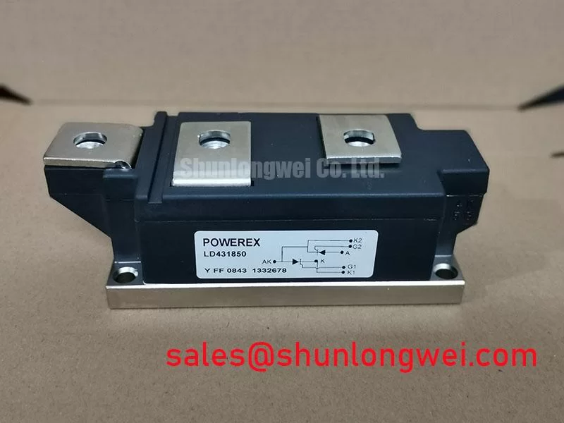
Before connection, verify the equipment record and module marking against LD431850, then compare the planned continuous-current duty with its 500.0 A official rating under the specified conditions and confirm that the mechanical interface accepts the POW-R-BLOK package.
The stated working-voltage designation is Standard Industrial Rating (Official Specification). No numerical voltage limit, gate characteristics, surge-current value, fuse I²t coordination value, thermal-resistance figure, terminal torque, or terminal map is stated in the supplied official data. These values must be verified from the original Powerex documentation and the equipment service record before a replacement is energized.
| Item | Value | Parameter Status |
|---|---|---|
| Part number | LD431850 | Official identification |
| Manufacturer | Powerex | Official identification |
| Continuous current rating | 500.0 A | Official Specification |
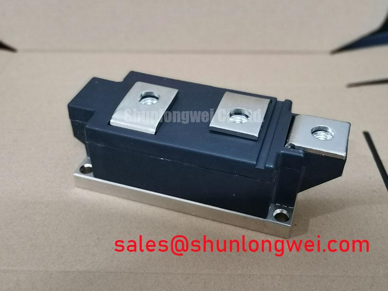
| Package | POW-R-BLOK | Official Specification |
| Working-voltage designation | Standard Industrial Rating | Official Specification |
LD431850 Operational Boundaries: Evaluating Power Factor Degradation and Harmonic Mitigation Limits
For a controlled AC-to-DC rectifier, begin with the firing-control record rather than assuming that a 500.0 A module rating alone establishes converter suitability. In a phase-controlled bridge, increasing firing angle changes the point at which each device is commanded into conduction. This reduces the useful average DC output while increasing the reactive-current burden seen by the upstream AC system. The resulting displacement of current relative to voltage can reduce power factor, and the non-sinusoidal current waveform creates harmonic content that must be evaluated at the system interface.
When reviewing an existing high-current green hydrogen electrolyzer DC power rectifier, compare the controller firing-angle range with measured AC line current, DC output current, transformer loading, and DC-link ripple. A low DC output reading can originate in the firing command, phase reference, transformer secondary balance, load-side conditions, or a device that is not transferring current correctly. It should not be assigned to the module from a single electrical symptom. Scope measurements should be referenced to the approved test procedure and compared with an equivalent healthy phase path where available.
The LD431850 is identified as a Powerex POW-R-BLOK device with an official 500.0 A current rating. That current figure is an electrical boundary for assessment, not a statement that every converter waveform, cooling arrangement, commutation condition, or overload sequence is acceptable. Engineers should reconcile measured RMS and average currents with the original rectifier design, including duty cycle and the cooling conditions present in the cabinet.
Fuse coordination needs the actual protective-device documentation. A fuse I²t value cannot be selected or declared compatible from the available module information because the official supplied data does not provide a module surge-current or I²t withstand rating. Review the fuse data, prospective fault current, bus arrangement, and controller fault-clearing path as one protection chain. The device should remain isolated while insulation clearances, creepage distances, terminal hardware, and protective-earth bonding are examined against the equipment design and applicable installation requirements.
Power factor correction equipment and harmonic filters are system-level items. Their practical behavior depends on source impedance, transformer configuration, firing strategy, load response, and the measured harmonic spectrum. The system integrator should validate those conditions at the intended operating states rather than infer filter performance from the rectifier module package. For manufacturer technical context on high-power semiconductor devices, consult Powerex High Power Semiconductor Modules.
LD431850 Operational Boundaries: Evaluating Interphase Transformer Current Balancing Limits
In rectifier systems using parallel paths, current sharing should be checked from the topology outward. A six-pulse bridge and a twelve-pulse arrangement do not present the same phase relationships, transformer requirements, or ripple pattern. Where parallel bridge sections are used for higher DC output, an interphase transformer can help accommodate instantaneous differences between otherwise similar rectifier paths. Its presence does not remove the need to verify branch-current balance under the actual firing sequence and load demand.
For equipment evaluated around the LD431850, establish whether each installed module occupies a controlled rectifier position, whether bridge sections are paralleled, and whether the original design calls for an interphase transformer. Record the current in each branch with suitable isolated instrumentation, observe the gate-command timing, and inspect transformer connections against the equipment schematic. A branch deviation may relate to phase timing, transformer polarity, commutation overlap, unequal bus resistance, connection condition, cooling variation, or the load itself. The appropriate response is to isolate evidence through comparative measurements, not to assume a single cause.
Positive temperature coefficient behavior is sometimes discussed when parallel power devices are considered, but it must not be treated as a universal guarantee of static or dynamic balance for this specific model. Current sharing remains a Design Consideration governed by the actual device characteristics, triggering behavior, layout symmetry, operating temperature, and transient conditions. The original manufacturer documentation is required before any claim about the parallel behavior of LD431850 can be made.
Terminal routing influences both steady-state and transient sharing. Keep corresponding branch paths physically comparable where the system layout permits, avoid unnecessary loop area, and verify that return conductors do not create unequal impedance between parallel sections. This is especially relevant around interphase-transformer connections, AC secondary busbars, and the DC output bus. A continuity check can identify an open or high-resistance connection, but it does not establish current-sharing quality; energized waveform and current measurements remain necessary.
Pro Tip: Maintain symmetrical power-bus routing around parallel rectifier paths, then confirm current balance and switching margins with controlled system testing.
For an electrolyzer rectifier, DC-current regulation and external process demand may alter the balance observed at different operating points. Testing should therefore include the command states used by the actual plant controller, subject to the site safety procedure. The module’s official 500.0 A rating should be considered alongside measured branch current, thermal conditions, and the original bridge configuration, rather than being multiplied into an assumed system current capability.
Transient Dynamics & Electrical Design: Turn-On Current Rise Limiting for LD431850
Before evaluating an RC snubber or a series saturable reactor, confirm the intended function of the LD431850 within the rectifier circuit and identify the actual transient observed. A controlled rectifier can experience commutation-related voltage stress, wiring-induced overshoot, source disturbances, and load-side events. The appropriate suppression network depends on measured waveform behavior, available device limits from the original Powerex documentation, bus geometry, transformer leakage characteristics, and the switching sequence defined by the controller.
RC snubbers are generally assessed as a Design Consideration to moderate rapid voltage transitions and associated ringing. Their component values cannot be responsibly prescribed from the supplied identification data because no official capacitance, resistance, dv/dt, peak-voltage, or energy-rating limits have been provided for this device. Selectors should use the original converter schematic where available, inspect the installed network for physical damage or changed electrical value, and validate any revised network through measured voltage and current waveforms under controlled conditions.
A series saturable reactor can also be considered where the established converter design uses it to shape current rise during fault or commutation events. Its effectiveness depends on the magnetic design, current waveform, source impedance, protection sequence, and the complete power path. It is not possible to state a suitable reactor characteristic for LD431850 from the official parameters available here. The system engineer should verify current-rise behavior against the protected circuit’s voltage boundaries and protection-clearing performance.
Gate-drive wiring, optocouplers, and digital isolators require similar restraint. Common-mode transient immunity is a property of the selected isolation component and the implemented drive board, not a specification established by the POW-R-BLOK package or the stated 500.0 A rating. Review the controller supply references, trigger return path, phase synchronization, and isolation barrier arrangement. An unexpected command can be related to control-reference movement, noise coupling, timing logic, connection integrity, or an external disturbance; verify with isolated measurement equipment against a known-good signal path.
The DC-link capacitor bank is another system-level contributor to transient behavior. Its physical placement, bus inductance, ripple-current capability, and connection integrity affect the waveforms seen by the rectifier assembly. The discussion of DC-link capacitor sizing and ripple-current calculation provides general context, but capacitor selection and placement must be verified against the rectifier’s original electrical design and measured duty.
Transient Dynamics & Electrical Design: Mechanical Mounting Torque Sequence and Thermal Considerations for LD431850
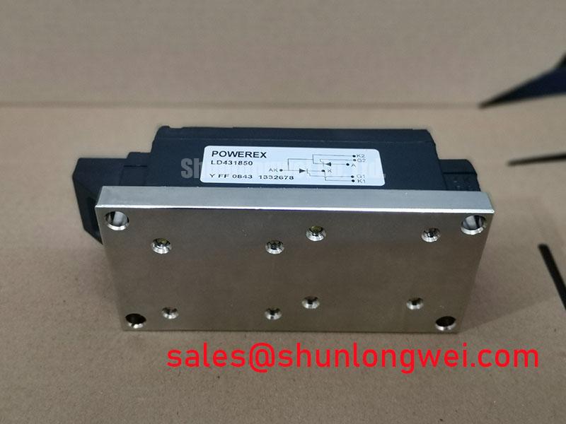
With power safely isolated and stored energy discharged according to the equipment procedure, inspect the POW-R-BLOK mounting surface before installing LD431850. Remove contamination only by methods approved for the equipment, check that the heatsink mating plane is free of damage, and confirm that the mounting pattern and terminal arrangement match the original assembly. The supplied official data identifies the package but does not state mounting-hole hardware, mounting torque, thermal interface thickness, baseplate flatness, or thermal resistance.
For this reason, a specific torque value must not be assigned to LD431850 without the original Powerex mechanical drawing or equipment documentation. Tightening sequence is a Design Consideration: use an even cross-pattern where the package and fixture require it, apply the documented hardware procedure, and avoid imposing uneven mechanical stress on the module body. The final torque and tooling are determined by the manufacturer documentation and the installed equipment hardware.
Thermal resistance from junction to case, often expressed as Rth(j-c), is not included in the supplied official parameters. It must therefore be treated as unverified for this product page. Engineers assessing thermal margin should obtain the manufacturer thermal data, inspect the heatsink and fan or liquid-cooling path, confirm airflow or coolant performance as applicable, and compare operating temperatures with the limits defined for the complete assembly. Surface temperature alone does not directly prove junction temperature.
Thermal paste should be handled as an integration material rather than as an assumed module characteristic. Apply it according to the approved service procedure so that contact pressure can spread the interface consistently without contamination of electrical terminals. Excess material, uneven clamp load, damaged heatsink surfaces, and loose bus hardware can each affect temperature rise or electrical reliability. The system should be tested after assembly with appropriately rated monitoring equipment and an approved commissioning sequence.
Safety Interlock Note: Do not loosen power terminals or remove the module until the equipment’s stored energy has been discharged and absence of voltage has been verified by the site-approved method.
When the rectifier operates near high-current duty, evaluate cooling as part of the complete assembly rather than assigning thermal performance to the module alone. The available 500.0 A official rating must be reconciled with the original cooling architecture, electrical waveform, enclosure conditions, and load profile. For broader technical context when reviewing cooling-path changes, see The Advanced Thermal Management Revolution.



