Content last revised on November 2, 2026
LM190E08-TLB2 Identification and Initial Inspection
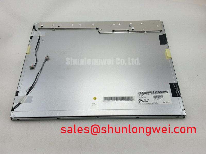
- Check the panel label for LM190E08-TLB2, then inspect the disconnected display cable for displaced contacts, damaged insulation, and incomplete connector engagement.
- Verify the panel supply against the specified 5.0 V typical input and inspect the separate CCFL inverter connections before applying power.
- Check bezel clearance and mounting alignment for pressure against the display frame or active viewing area.
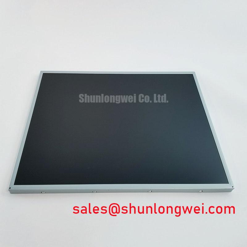
- For a dark screen, inspect for a faint image under external illumination to help separate backlight symptoms from image generation faults.
The LG Display LM190E08-TLB2 is a 19.0-inch SXGA LCD display with a 30-pin, dual-channel LVDS interface and four CCFL backlight lamps. Its electrical interface, lamp connections, and mechanical envelope are separate compatibility checks during replacement assessment. A matching diagonal alone does not establish interchangeability.
| Feature | Official Specification |
|---|---|
| Manufacturer and model | LG Display LM190E08-TLB2 |
| Screen size | 19.0 inches |
| Resolution | 1280(RGB) × 1024, SXGA |
| Aspect ratio | 5:4 horizontal to vertical |
| Luminance | 300 cd/m² typical |
| Contrast ratio | 700:1 typical, transmission mode |
| Viewing angle | 80°/80°/80°/80° typical, CR ≥ 10 |
| Display colors | 16.7 million, 6-bit + Hi-FRC |
| Signal interface | LVDS, 2 channels, 8-bit, 30-pin connector |
| Backlight | 4 CCFL lamps |
| Panel supply | 5.0 V typical |
| Outline dimensions | 396(H) × 324(V) × 17.5(D) mm |
Connector pin assignments, lamp operating limits, mounting hardware, tightening torque, and operating temperature limits require the applicable panel drawing and electrical specification for integration.
Suppressing Localized Thermal Gradients to Prevent Chronic Optical Yellowing (Color Shift)
Map edge temperatures while displaying a uniform neutral image, then compare any warm region with the location of persistent discoloration. Design Consideration: localized heat near the backlight or adjacent electronics can influence optical uniformity, but yellowing alone does not establish which optical layer or electrical assembly is responsible. Compare the cold image with the stabilized image under unchanged brightness and viewing conditions.
Engineering Recommendation: when evaluating enclosure heat spreading, inspect contact paths, ventilation openings, and proximity to heat-producing equipment before changing the mechanical assembly. Aluminum rails should be assessed against the actual chassis geometry and electrical clearances; their dimensions should follow measured thermal behavior and enclosure constraints. Avoid transferring mounting pressure into the display stack while improving heat flow.
This panel uses CCFL illumination, so LED lumen maintenance metrics do not describe its backlight performance. Record edge shading, color balance, and brightness repeatability instead of assigning an unsupported service life. For broader enclosure and environmental assessment, Industrial Display & HMI Solutions provides related integration context.
Design Consideration: slower grayscale transitions during cold operation should be evaluated separately from lamp startup behavior. Compare motion trails and stationary test patterns only within the approved equipment temperature range. Any enclosure heating arrangement requires system temperature control and validation against the panel operating limits.
High-Voltage Striking Potential & Secondary Coil Insulation Testing
Separate the 5.0 V panel supply measurement from inverter output testing when investigating a black screen. The four CCFL lamps require a compatible inverter, and lamp ignition conditions differ from sustained operation. Engineering Recommendation: use the inverter service procedure and appropriately rated measurement equipment to assess startup behavior; select insulation test conditions from the inverter documentation rather than applying an arbitrary test voltage to connected electronics.
Field Alert: Disconnect equipment power and allow stored energy to discharge before reconnecting the LVDS cable or CCFL lamp leads.
Design Consideration: a brief flash followed by darkness can involve lamp loading, inverter protection, supply instability, or connection problems. Correlate the visible behavior with inverter enable, brightness control, and supply measurements. Acoustic noise also requires inspection of the driver and mechanical mounting; it does not independently identify a defective lamp.
For image loss with working illumination, trace the controller output to the panel’s dual-channel LVDS input. Check channel mapping, clock integrity, and cable continuity against the host configuration. LVDS uses differential signaling; a TTL output requires a suitable conversion stage. Engineering Recommendation: preserve the intended differential impedance through cable and connector transitions, then evaluate jitter and data timing at the receiver against the applicable interface requirements.
The LM201U05-SLL1 can be considered separately when comparing display assemblies and their associated drive electronics. It is a display model, and its interface and backlight requirements need their own compatibility assessment.
Chassis Fastener Torque Sizing to Reduce Optical Mura Defects
Check the 396 × 324 × 17.5 mm outline against the chassis opening, rear clearance, and mounting points before tightening the assembly. Design Consideration: an uneven bezel or distorted support can introduce localized pressure and visible nonuniformity. Inspect a dark uniform image before installation and after securing the display to distinguish pre-existing shading from assembly-related changes.
Engineering Recommendation: establish fastener type and tightening torque from the mounting drawing and chassis specification. Bring mounting points into contact progressively while checking frame seating. A generic screw size or torque range cannot establish the allowable load for this panel. Cable routing should also leave the connector free from chassis-induced tension.
The 5:4 aspect ratio matters when assessing replacement geometry and host image scaling. The reference on Display Aspect Ratio and Standard Screen Form Factors explains the relationship between image proportions and display shape. For a precision electronic test and measurement instrument, engineers should check waveform grids, labels, and touch coordinates at native resolution before approving integration.
The related LM190E08-TLG5 is a comparison candidate during replacement assessment. Compare its connector assignment, signal mapping, mounting drawing, lamp connections, and optical specifications with the installed assembly before deciding whether it is interchangeable.
Dynamic Contrast Ratio Stabilization & Liquid Crystal Birefringence Temperature Tracking
Display grayscale ramps and neutral patches at fixed brightness to distinguish contrast variation from backlight drift or controller processing. The specified 700:1 typical contrast ratio is a panel optical specification, not a dynamic contrast guarantee. Its 300 cd/m² typical luminance also does not establish readability under direct sunlight.
Design Consideration: reflected ambient light reduces perceived black depth. Evaluate the assembled cover window, reflections, and viewing position under the intended lighting. Anti-glare or antireflection treatment belongs in the complete optical assessment; neither treatment should be attributed to this model without a corresponding specification.
The stated viewing angles are 80° in each direction at CR ≥ 10. Assess grayscale visibility from the actual operator position rather than inferring panel technology from these angles. The 6-bit + Hi-FRC color specification and the 8-bit LVDS interface describe different parts of the display path.
Engineering Recommendation: investigate shifted grayscale by checking host gamma settings, supply stability, and accessible timing-controller reference measurements against the service procedure before adjusting calibration. If artifacts coincide with nearby drive switching, compare signal and supply behavior with that equipment enabled and disabled. Assess touch sensitivity separately through the installed touch controller, especially with gloves or surface moisture. For temperature-dependent motion trails, compare transitions at stable temperatures within approved limits while holding the test pattern and controller settings constant.