
Content last revised on September 10, 2026
Optical Luminance Degradation Assessment and Backlight Retrofit Verification
For an LM32004 evaluation, begin with a full screen illumination check using a known stable video source from the original controller or an approved test fixture. Display black, white, red, green, blue, and mid gray fields while observing the panel from normal viewing distance and at oblique angles. This process can reveal dark areas, inconsistent brightness, color shifts, intermittent illumination, or areas that change when the enclosure is lightly moved.
A dim image is not sufficient evidence that the LCD panel itself has failed. If a faint image becomes visible under external illumination, the panel may still be receiving image data while the light source or its driving circuit requires investigation. If no image appears, verification should extend to the host board, panel supply sequencing, cable engagement, and data path. The system integrator should verify the required supply voltage and backlight arrangement from the original panel documentation rather than assuming a particular lamp or LED architecture for the LM32004.
Backlight modernization should be treated as a system level engineering evaluation, not as an automatic panel repair. A replacement light source can alter optical distribution, electrical loading, dimming behavior, thermal conditions, and mechanical stack height. Any conversion discussion should therefore begin by documenting the original enclosure geometry, the existing power circuit, the brightness control method, and the panel’s optical performance in the target equipment.
Design Consideration: constant current regulation is commonly evaluated for LED illumination because it helps control light output consistency as operating conditions change. That principle does not confirm that the LM32004 uses an LED backlight, nor does it establish a compatible retrofit arrangement. Engineers should measure the host system’s backlight output behavior and confirm the replacement assembly’s electrical and optical characteristics before modification.
For industrial HMI service, compare a suspect screen against a known good reference under similar ambient conditions. Examine whether brightness remains stable after the panel has been powered for an appropriate observation period. A progressive decrease in uniformity may point to an illumination subsystem issue, while localized patchiness can also arise from optical layers, mechanical pressure, or contamination. The observation should be recorded as a visual result rather than converted into an unsupported lifetime prediction.
💡 Bench Tip: Disconnect power and use appropriate ESD controls before releasing the display cable latch, then insert the flexible cable squarely and lock it without forcing the contact end.
For equipment repair planning, maintain the original interface board and bezel arrangement until panel compatibility is confirmed. A display assembly that appears physically similar can still differ in connector position, signal mapping, timing requirements, or illumination control. If another industrial display is being assessed as a comparison candidate, the LM190E08-TLG6 should be evaluated against the original machine requirements rather than treated as a direct substitute for the LM32004.
Mechanical Stress Screening Around the Glass, Bezel, and Flexible Cable
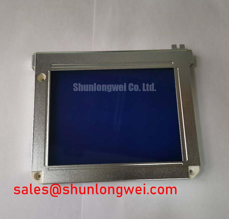
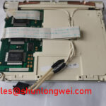
Mechanical screening begins before electrical test. Place the LM32004 on a clean, flat, static controlled surface and inspect the display face under diffuse lighting. Look for corner stress marks, pressure halos, chips near the edge, frame distortion, and cable folds close to the connector transition. These observations matter because a panel can appear intact at rest while showing intermittent lines, flicker, or color disruption once installed in a constrained front panel assembly.
Run a sequence of solid primary color fields, black, white, and neutral gray. Observe the complete active area during each field. Fixed vertical or horizontal lines that remain visible across multiple patterns can indicate a panel side issue, but engineers should first confirm that the source signal and cable contacts are stable. If the line changes when the cable is carefully stabilized, the cable path or connector engagement deserves closer inspection. Avoid pressing directly on the glass to provoke a symptom, as this can create new mechanical stress.
A flashlight inspection performed at an angle can help separate apparent illumination variation from visible surface damage. Under a dark field, sweep a low intensity flashlight along the display face and bezel boundary. Reflections can expose scratches, particulate contamination, compression patterns, or frame contact points that are less obvious under normal room lighting. This is a diagnostic aid, not proof of a single failure mechanism.
Design Consideration: the mechanical enclosure should support the module through its intended mounting features and should not impose uneven pressure on the display face or cable exit. CNC operator panels can experience repeated keypad actuation, door movement, vibration, and service access. Robot teach pendants can experience handling loads around the cable entry and front bezel. In either case, the repaired assembly should be checked with the cover installed because an otherwise stable screen may change behavior after enclosure compression.
Flexible printed cables require particular attention. A sharply bent cable, a cable routed across an unrelieved edge, or a connector that is partially latched can produce intermittent image loss that resembles a panel defect. Route the cable with adequate freedom for the equipment housing to close without pulling it. When replacing a panel, preserve the original cable path where possible and confirm that no clamp, foam pad, shield, or cover screw moves the cable after final assembly.
Long term static HMI pages also merit visual inspection. Alarm banners, coordinate readouts, menu bars, and fixed machine graphics can make subtle nonuniformity more visible over time. When a retained image or tonal difference is reported, cycle through neutral full screen patterns and compare the behavior after normal display use. The result may be influenced by panel operating conditions, image content, drive electronics, or optical history, so the panel should not be assigned a single cause without comparative testing.
Constant Luminance Control, Thermal Paths, and Signal Integrity Checks
The LM32004 should be integrated only after its original documentation has been matched to the host system. The verified product identity establishes it as a Sharp TFT LCD module, but does not provide approved values for input voltage, signal standard, timing, backlight current, brightness control, or connector pinout. The system integrator should verify each required electrical value from the original panel documentation and the equipment controller before connection.
During bench testing, observe the order in which the host supplies logic power, image data, and illumination control. An all white display, a temporary flash, or residual image behavior during shutdown can be influenced by system sequencing and controller behavior. Test against a known good signal path whenever possible. The goal is to determine whether the symptom follows the panel, the cable, the controller board, or the assembled machine state.
Design Consideration: signal pairs and their return paths should be routed in a controlled manner when the host uses high speed differential display signaling. The relevant impedance, pair matching, shielding arrangement, cable length, and grounding scheme are determined by the original interface standard and the equipment design. Engineers should verify waveform quality at the panel connector against the known good path, especially where a repaired CNC control enclosure contains switching power supplies, servo drives, contactors, or other sources of electrical noise.
Do not infer an interface from connector appearance alone. Industrial display modules can use different signaling conventions and connector populations even when their external form is similar. Confirm cable pin order, keyed orientation, enable lines, and ground references before applying power. If an adapter board is considered, its compatibility must be established from documented signal definitions and electrical requirements, not from mechanical fit.
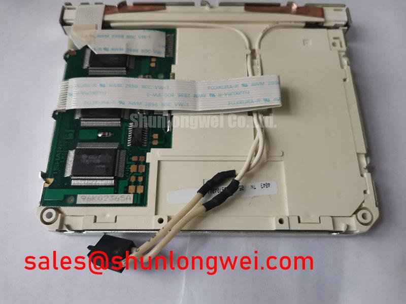
Thermal conditions should be observed at the assembled product level. A tightly enclosed operator terminal can retain heat around the panel rear surface, illumination electronics, and controller board. Where the enclosure uses conductive rails, thermal pads, or a rear support plate, reinstall those parts in their intended locations. Their presence may affect physical stability and heat transfer, but the exact thermal performance of the LM32004 cannot be claimed without applicable factory data.
When diagnosing brightness variation, inspect for changes that correlate with enclosure temperature, cable movement, supply behavior, or display content. A stable test image with unstable illumination may suggest a different inspection path than a display with image corruption. Record the conditions under which the fault occurs, including whether it is present at power up, after warm operation, while the pendant is moved, or only after the front cover is fitted.
For technicians building a repeatable incoming inspection process, the broader testing principles in The Ultimate Guide to Industrial TFT LCD Technology can support structured review of interface confirmation, optical observations, mechanical fit, and environmental conditions. The original machine documentation remains the controlling reference for LM32004 integration.
Cold Start Image Response and Power Sequencing Validation
Cold start testing should reproduce the actual behavior of the equipment as closely as possible. Install the LM32004 using the intended cable route and mounting arrangement, then observe the first image presented by the original controller. Check for delayed image appearance, temporary color distortion, flicker, partial display activation, or persistent artifacts. Repeat the observation after the machine has reached its normal operating condition. A difference between cold and warm behavior can guide further testing, but it should not be treated as proof of a particular internal panel condition.
Liquid crystal response can visibly change with temperature in display technologies, while the effect seen in a specific machine also depends on the display controller, timing configuration, supply sequence, and enclosure environment. For the LM32004, no verified operating temperature range or gray to gray response specification is provided in the available factory information. Any temperature qualification must therefore follow the original Sharp documentation and the equipment manufacturer’s operating requirements.
Power cycling should be controlled and repeatable. Test the panel with the original controller and observe whether a symptom occurs consistently after full shutdown, after a normal restart, or after cable reseating. Avoid repeated uncontrolled connection and disconnection while energized. A residual image, white screen, or no display condition may involve panel initialization, supply stability, data signaling, or illumination control. Comparing the panel with a known good unit in the same host assembly is more informative than making a diagnosis from a single symptom.
Mechanical vibration checks should also be conservative. With the equipment de energized, confirm that the bezel, mounting points, cable retention features, and rear supports are secure. After reassembly, operate the equipment through normal nonhazardous handling movements and observe whether image stability changes. If a fault appears during movement, inspect the cable path, connector lock, enclosure pressure, and controller board connection before attributing the result to the display module.
For CNC operator panels and robot teach pendants, use the LM32004 only after confirming the exact interface, mounting arrangement, optical area, controller timing, and power requirements against the removed display and original machine records. This verification preserves the distinction between a panel replacement decision and a broader controller or wiring fault investigation.