

Content last revised on October 15, 2026
Restoring Missing Horizontal Display Rows / Vertical Columns Caused by Flex Cable Delamination
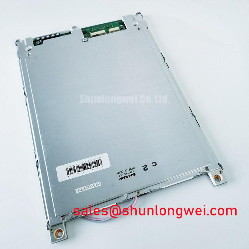
I record the position of missing rows and columns on a stable test pattern before disturbing the LM64C142 cable or bezel. A line that stays fixed across different images warrants a different investigation from an entire image that shifts, repeats or intermittently disappears. Cable damage, connector contamination, controller timing and panel interconnect faults can produce overlapping symptoms; missing lines alone do not establish flex delamination.
Design Consideration: Inspect the accessible cable contacts, connector latch and mounting points with power disconnected. Look for uneven insertion, damaged conductors, displaced strain relief and enclosure features that load the cable when the cover closes. Compare the assembled cable route with its unloaded position. A connection that works on an open bench but fails after enclosure installation deserves mechanical inspection before controller adjustments.
Where the assembly documentation identifies an elastomeric connector, alignment and compression belong to the specified mechanical stack, not an improvised pressure adjustment. Increasing bezel force can distort the optical assembly without repairing a damaged interconnect. Bonded flex connections should not be treated as serviceable plug connectors, and pressing the glass is not a reliable diagnostic method.
Bench Tip: Disconnect power, apply ESD precautions and seat the ribbon squarely before securing its latch; never reseat it while energized.
For replacement assessment, compare the Sharp LM64C142 against the host drawing, connector assignment and controller requirements. The LM8V302 provides another display reference for comparison, not an established interchangeable replacement. A factory automation machine-tool HMI operator terminal is a potential compatibility assessment context, subject to those electrical and mechanical checks.
Data Setup & Hold Time Margin Verification on High-Capacitance Flat Ribbon Flex Cables
Capture the data and clock signals at the receiving connector rather than judging interface quality from the controller output alone. The cable, connector and probe loading affect the waveform that reaches the display. Compare a failing configuration with a known-good cable arrangement while keeping the displayed pattern and measurement method consistent.
Design Consideration: On a documented passive-matrix interface, signals identified as FLM, LP and CP commonly represent frame, line and data-clock functions. Their names do not establish the LM64C142 pin assignment, data width or sampling edge. Use the matching connector drawing and timing chart to identify the active transitions, then examine whether data remains stable around the receiving edge under actual operating conditions.
Rounded edges, ringing and relative clock movement can reduce setup and hold margin. Short probe connections and an appropriate reference point help distinguish interface behavior from measurement artifacts. If the image changes when servo equipment operates, correlate the disturbance with interface waveforms and supply behavior. Cable routing, return-path continuity and enclosure bonding are system-level investigation points, not proof that the panel itself has failed an EMC requirement.
A parallel display interface must not be treated as LVDS simply because a replacement controller offers an LVDS output. Signal format, logic levels, timing and connector assignment must agree across the complete connection. Differential termination rules do not transfer automatically to a single-ended ribbon bus.
During startup and shutdown, compare logic supply, display-bias and control-signal behavior with the prescribed sequence. Passive-matrix operation depends on appropriate alternating drive; sustained unintended DC across the liquid crystal is undesirable. Correct the controller or supply sequence using measured behavior rather than imposing a generic bias order or delay.
Polarizer Delamination Bubble Mitigation and Optical Retardation Film Inspection under Workshop Lighting
Display uniform dark and bright fields, followed by alternating pixel patterns, while keeping viewing direction and ambient illumination repeatable. Record fixed spots, streaks, bubbles and brightness gradients separately. A defect visible on every pattern is not automatically a failed pixel: surface contamination, optical-layer damage and illumination nonuniformity can occupy the same apparent location.
Design Consideration: Inspect first with normal illumination, then with oblique workshop lighting to reveal surface lifting and edge disturbance. Compare observations with the backlight operating and with external illumination where the assembly permits. This helps separate illumination defects from changes in the optical path without asserting an undocumented reflective or transflective construction.
Do not assign a particular polarizer chemistry, adhesive formulation or retardation-film structure to the LM64C142 from appearance alone. Aging, environmental exposure and mechanical stress are investigation categories, not confirmed causes. Photograph the affected area under repeatable conditions and check whether enclosure pressure changes its appearance during controlled assembly inspection.
Cleaning should follow the approved procedure for the exposed surface. Connector-cleaning solvents are not automatically suitable for polarizers, optical coatings or bonded edges. Attempting to flatten a bubble with localized pressure or heat can obscure the original condition and damage adjacent layers.
Backlight color variation should also be distinguished from viewing-angle-dependent contrast. If the host includes a separate touch overlay, glove response and wet-surface behavior belong to that overlay and its controller, not to the bare LCD specification. The distributor’s The Ultimate Guide to Industrial TFT LCD Technology offers broader comparison context, but TFT-specific descriptions should not be transferred to this passive-matrix baseline.
CCFL Resonant Inverter Striking Potential & Ignition Arc Fault Prevention
Identify the installed backlight assembly and its matched driver before connecting a test inverter. For a documented CCFL installation, starting behavior and running behavior require separate evaluation: a lamp that briefly illuminates and then extinguishes can reflect lamp, wiring, inverter or protection-circuit problems. The symptom does not identify a single failed part.
Design Consideration: Examine accessible high-voltage leads and connectors for damaged insulation, contamination, tracking marks and strain near terminations. Starting voltage, operating voltage and regulated lamp current must come from the matched lamp and inverter specifications. Generic ignition ranges are not LM64C142 ratings and should not become bench acceptance limits.
Use measurement equipment rated for the actual waveform and voltage. A resonant inverter output cannot be assessed safely or accurately from a casual meter reading. Clearance, creepage and insulation assessment depend on the complete assembly and applicable equipment requirements; increasing the starting drive to overcome intermittent ignition is not a substitute for locating the fault.
The LM64C09P is a related display reference when comparing host display arrangements, not a backlight driver or a confirmed electrically compatible accessory. Manufacturer-level display information is accessible through the Sharp Display Solutions Official Portal and Sharp Devices Europe Industrial Display Solutions; model-specific service decisions still require the matching assembly documentation.
After correcting an identified wiring or driver fault, repeat cold-start and steady-illumination checks with the enclosure assembled. Record ignition consistency, visible flicker, brightness distribution and any protection shutdown alongside the test conditions so the next technician can reproduce the assessment.