

Content last revised on September 23, 2026
LM64P839 Replacement Inspection
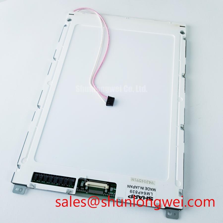
Start the replacement inspection by checking the LM64P839 identification marking, examining the TFT-LCD module for edge damage, and comparing the existing panel connector and mounting pattern with the original equipment documentation. The available factory context identifies this unit as a Sharp Industrial Grade LCD/HMI Panel in a TFT-LCD Display Module package. Electrical values, interface assignment, backlight architecture, optical dimensions, and operating limits should be confirmed against the panel documentation supplied with the equipment before power is applied.
High-Voltage Striking Potential and Secondary Coil Insulation Testing
The LM64P839 is documented here as a TFT-LCD display module, but the supplied factory data does not confirm whether the original assembly uses a CCFL inverter, an LED backlight driver, or a particular high-voltage secondary circuit. A replacement assessment should therefore begin with the original panel label, inverter board, connector wiring, and service documentation rather than assuming a backlight topology.
Where the installed display uses a CCFL inverter, the service engineer should treat the secondary circuit as a high-voltage assembly and follow the equipment manufacturer’s discharge and insulation-testing procedure. The commonly discussed cold-start range of 1500 to 1650 Vrms is not an official LM64P839 specification in the supplied data and must not be applied as a device rating without confirmation from the original panel documentation. The same principle applies to any claimed lamp half-life, MTBF, or brightness-decay curve. No verified 50,000-hour half-life or MTBF value is assigned to this model by the available information.
For an LED-based replacement arrangement, the system integrator should verify the required supply voltage, current regulation method, enable signal, fault response, and dimming interface from the original panel documentation. A constant-current driver may require open-load and short-circuit protection, but the correct threshold and protection sequence are system-specific. During troubleshooting, measure the driver output only with probes and instruments rated for the circuit, and compare enable, feedback, and fault signals with a known-good assembly.
When a display remains dark while the control system reports normal operation, inspect the complete signal chain. Confirm that the display supply is present, that the backlight enable command reaches the driver, and that the driver does not enter protection after startup. A dark screen may also result from a missing video signal, an incorrect power sequence, connector contamination, or an incompatible replacement harness. An oscilloscope inspection of the known-good signal path is more reliable than assigning a single cause to the symptom.
Designers evaluating the LM64P839 for a CNC operator panel or robot teach pendant should document the original backlight arrangement before ordering associated driver hardware. The linked LMS700KF01-001 may be reviewed as a related display solution reference, but compatibility with the LM64P839 must be established from connector definitions and electrical documentation.
Industrial Bezel Mechanical Envelope Tolerances and Mounting Screw Torque Optimization
Mechanical replacement work should start with a dimensional comparison of the installed bezel opening, visible display area, connector clearance, cable bend path, and rear support points. The confirmed product category is a TFT-LCD display module; the supplied data does not include the module’s external length, width, thickness, active area, mounting-hole pitch, or bezel envelope. These dimensions must be taken from the original panel drawing or measured from the removed unit.
Uneven clamping can place local stress on the display assembly and may produce pressure-related optical non-uniformity, edge shading, or mechanical damage. This is a general integration consideration, not a factory specification for the LM64P839. Fasteners should be tightened progressively in a cross-pattern where the chassis design permits, allowing the bezel and support frame to settle evenly. The correct fastener size, torque, washer arrangement, and bracket stiffness remain determined by the equipment manufacturer’s mechanical drawing.
The frequently used M3 torque range of 0.35 to 0.45 N·m is not verified as an LM64P839 mounting requirement in the available factory information. It should not be treated as a mandatory value for this module. If the original service manual specifies a torque, use that value; otherwise, the maintenance team should establish a controlled starting point through a mechanical fit check while observing the panel for distortion and optical change.
Maintenance Note: Inspect the bezel sealing gasket and cabinet airflow path during scheduled service, because damaged sealing material or blocked ventilation can increase contamination and thermal stress around the display assembly.
For equipment exposed to dust, coolant mist, or frequent operator contact, check whether the cabinet seal compresses uniformly around the viewing aperture. A gasket that is twisted, cut, or locally over-compressed may allow contamination to reach the panel area. Do not add adhesive, foam, or spacer material unless the cabinet design authorizes it, since an improvised support can transfer force into the display edges.
The LM64P10 can be used as a same-category reference during dimensional and resolution cross-checking, but it should not be treated as a drop-in substitute without verifying active area, connector position, electrical interface, mounting geometry, and backlight requirements. A replacement decision should be based on the machine’s original drawing and a controlled bench comparison.
LCD Grayscale Variation and Optimal Viewing Direction Alignment
The supplied information does not confirm the LM64P839’s LCD cell mode, native resolution, viewing-angle specification, surface treatment, touch technology, or grayscale response. The product should therefore be evaluated by observing the actual image from the operator’s normal position and by checking the original panel datasheet before making claims about TN, IPS, MVA, anti-glare, or anti-reflective performance.
If the installed panel uses a TN-type cell, grayscale tones can vary with viewing direction. This is a general display engineering consideration rather than a confirmed LM64P839 characteristic. During a CNC or robot pendant evaluation, display mid-tones, alarm colors, thin characters, and low-contrast status indicators from the normal operator position. Then repeat the check above, below, and to each side of the intended viewing axis. Any change should be recorded together with ambient lighting and screen brightness settings.
High ambient illumination can make a display appear low contrast even when the video electronics are operating correctly. A surface described as AG or AR should be confirmed from the original optical specification; the supplied factory context does not verify either treatment for this model. The integrator should assess reflections from machine guarding, overhead lighting, and protective windows before selecting a replacement panel or adding a cover lens.
Do not assume that the LM64P839 accepts a particular PWM frequency, duty-cycle range, TTL signal, or LVDS signal format. The available information does not provide the connector pinout or timing table. When a backlight controller is involved, verify its dimming method and frequency against the original driver documentation. Audible noise, visible flicker, or uneven brightness should be investigated by checking the driver waveform, grounding, enable timing, and load condition rather than by changing one parameter without measurement.
Touch capability also requires direct confirmation. The supplied product description identifies an LCD/HMI panel but does not specify a resistive or capacitive touch layer, glove performance, water rejection, controller interface, or touch sensitivity. For a robot teach pendant, test the complete assembly with the intended gloves and with the expected level of surface moisture. A failure to register input may involve the touch controller, protective overlay, calibration data, grounding, or software configuration, so the display image and touch path should be tested separately.
EMC evaluation belongs to the completed panel and equipment assembly. The LM64P839 itself should not be described as independently certified for an enclosure-level EMC standard. When installed near servo drives or switching power supplies, keep display signal and backlight wiring routed according to the cabinet design, separate noisy power conductors where practical, and verify the result through system-level testing. The equipment manufacturer remains responsible for the final compliance assessment.
Aluminum Heat Spreader Sizing and Thermal Interface Placement Along Narrow Display Edges
Thermal work should begin with an inspection of the cabinet temperature, rear clearance, connector area, and airflow route around the display. The supplied official context does not state the LM64P839 operating temperature range, storage temperature range, power consumption, backlight type, LED lifetime, or thermal resistance. Aluminum rails, heat spreaders, or thermal pads must therefore be treated as system-level design options rather than confirmed product requirements.
A heat-spreading rail can be considered when a measured hot region develops near a narrow display edge or adjacent driver board. Its placement should avoid the active display area, connector contacts, flexible cables, and any moving bezel component. The mechanical designer should verify that the rail does not introduce point loading or obstruct the cabinet’s intended airflow. Thermal interface material should be selected for electrical isolation, compression behavior, surface compatibility, and long-term stability according to the equipment design.
Claims involving PMMA yellowing, L70, B50, or LED operational longevity require a verified backlight construction and an applicable manufacturer test method. Those values are not established for the LM64P839 by the supplied factory data. During qualification, record display brightness, cabinet temperature, driver current, and the location of thermal sensors under the actual enclosure conditions. A measured trend can support an engineering decision; it should not be converted into a guaranteed service-life figure without authoritative test data.
The same caution applies to TTL and LVDS timing. The available information does not provide the LM64P839 transmitter type, receiver pinout, data rate, clock tolerance, setup time, hold time, or differential impedance requirement. The system integrator should identify the interface from the original documentation, use the specified cable and termination arrangement, and verify the received waveform at the panel connector. If an LVDS link is confirmed, controlled differential routing and the manufacturer’s prescribed termination should be followed; a generic impedance assumption cannot establish compatibility.
When an image shows intermittent lines, color instability, or startup dropouts, inspect the connector seating, cable strain, supply stability, grounding, and clock or data quality together. An oscilloscope or suitable differential probe can help compare the suspected path with a known-good panel. Thermal cycling should be performed only within the confirmed limits of the original equipment and panel documentation, with condensation control during transitions.
For long-term HMI planning, the reference material at Industrial Display & HMI Solutions provides broader context for industrial display integration. The LM64P839 remains a Sharp TFT-LCD display module whose final suitability depends on verified electrical, mechanical, optical, thermal, and interface compatibility with the CNC operator panel or robot teach pendant.