Content last revised on September 12, 2026
LMG7410PLFC-A HITACHI Display Module Overview
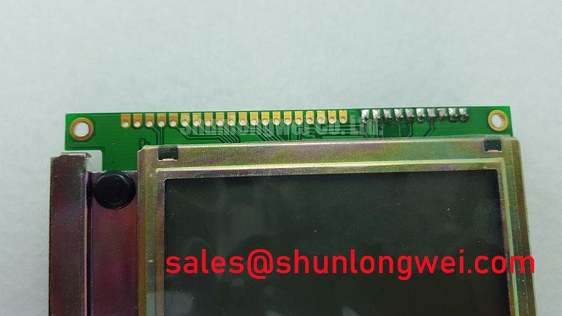
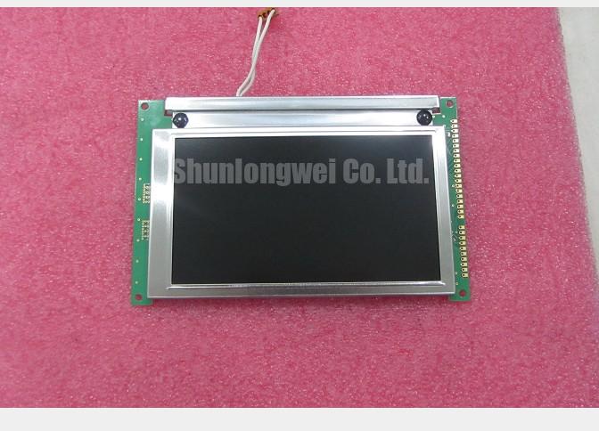
Before connecting a replacement display, isolate power, inspect the bezel and connector area, and compare the panel identification label with the equipment service record. The LMG7410PLFC-A HITACHI is identified in the supplied factory context as a KOE / Hitachi Industrial Grade LCD/HMI Panel in a TFT-LCD Display Module format. Its supplied specification record confirms the product category and construction class, but it does not provide a complete electrical pinout, native resolution, viewing angle, luminance value, interface voltage, backlight type, or environmental rating. Those items should be verified against the original panel documentation before installation.
| Model | LMG7410PLFC-A HITACHI |
| Manufacturer identity | KOE / Hitachi |
| Product category | Industrial Grade LCD/HMI Panel |
| Package or assembly form | TFT-LCD Display Module |
| Specification status | Official Factory Spec Verified within the supplied product record |
For maintenance teams, this distinction matters. A TFT-LCD module is only one part of the display assembly. The host system may also include a controller board, timing controller, backlight driver, cable harness, mounting frame, touch layer, and protective window. Before approving a replacement for a railway passenger information system or cab signalling display, engineers should confirm the complete system interface rather than relying on the model number alone.
Logic Supply Voltage Sequencing and Driver Interface Verification
Start the electrical inspection with the original display disconnected from the host controller. Record the connector keying, cable orientation, signal labels, and the sequence in which logic power, display enable, backlight enable, and video data become active. The supplied product record does not confirm whether this specific module requires a 3.3 V logic rail or a 5.0 V logic rail. The system integrator should verify the required supply voltage from the original panel documentation and measure the installed controller output before applying power to the replacement.
Power sequencing is a system integration consideration rather than a confirmed factory parameter for this model. If the controller drives data before the panel logic rail is stable, the display may show an incomplete image, unstable start-up behavior, or intermittent recovery after a power cycle. Engineers should compare the original timing relationship between logic supply rise, reset, display enable, and video transmission. The supplied engineering brief identifies a target rise-time review window of 0.5 ms to 10 ms; this should be treated as an integration verification point, not as a confirmed electrical specification of the LMG7410PLFC-A HITACHI.
Where the host uses LVDS, inspect the differential pairs for consistent routing, clean reference return paths, and connector seating. A nominal 100 ohm differential characteristic impedance is a common LVDS design consideration for the transmission path, but the system designer must verify the actual cable, PCB, termination, and receiver requirements from the controller documentation. If the host uses TTL or another parallel interface, do not assume LVDS compatibility from the TFT-LCD format alone. Confirm the interface family, bit mapping, clock polarity, data width, and signal direction before powering the panel.
Split-screen images, shifted columns, incorrect grayscale, or unstable color blocks can have several possible causes, including data mapping mismatch, cable orientation, timing-controller configuration, signal integrity, or a host-board fault. Use an oscilloscope at the known-good signal path and compare clock quality, differential amplitude, and data relationship with the replacement connected under the same conditions. The supplied record does not establish a JEIDA or VESA mapping for this model, so the correct mapping must be taken from the original panel documentation or verified through the equipment manufacturer’s service information.
For a same-size or same-resolution replacement evaluation, engineers may also review TX23D11VM2BAA as a separately listed compatible device. Compatibility remains conditional on mechanical dimensions, connector arrangement, interface timing, backlight control, optical requirements, and host firmware.
Backlight Assessment and Secondary Insulation Checks
Do not infer the backlight technology from the TFT-LCD designation. The supplied factory record does not confirm whether the LMG7410PLFC-A HITACHI uses a cold-cathode fluorescent lamp, an LED backlight, or a particular driver architecture. Inspect the original display assembly for the backlight connector, driver board, enable signal, brightness control method, and service labels. The system integrator should verify the backlight type from the original panel documentation before selecting a driver or adapting the harness.
If the original assembly contains a CCFL inverter, high-voltage ignition and secondary insulation require a dedicated safety procedure. The supplied engineering brief identifies 1500 Vrms to 1650 Vrms as a potential cold-ignition assessment range for the relevant system architecture. This is not a confirmed rating of the LMG7410PLFC-A HITACHI. Any insulation or withstand test must follow the equipment manufacturer’s approved procedure, use suitable guarded test equipment, and account for clearance, creepage, transformer construction, connector spacing, and discharge time.
A replacement that uses a constant-current LED driver must not be connected to a CCFL harness without confirming electrical compatibility. LED current regulation, enable polarity, dimming method, connector pin assignment, and thermal behavior are system-level requirements. Engineers evaluating PWM dimming should verify the driver’s specified frequency range and duty-cycle response rather than transferring values from another panel. The supplied engineering brief mentions a possible 200 Hz to 1 kHz evaluation range and a 1000:1 dimming objective for a driver architecture, but these values are not factory specifications for this display module.
Visible flicker, acoustic noise, uneven brightness, or delayed ignition should be investigated across the complete backlight circuit. Check the driver output with an appropriate probe, inspect transformer and connector condition where applicable, and compare the enable and brightness-control waveforms with a known-good assembly. A display that illuminates briefly and then turns dark may involve protection behavior, lamp ageing, driver shutdown, connector resistance, or a host control fault; the symptom alone does not identify a single failed part.
Do not treat a projected backlight service life or half-life value as confirmed for this model. No authoritative lifetime figure was supplied for the LMG7410PLFC-A HITACHI, so field operating hours, MTBF, and failure-rate claims should be obtained from the applicable factory datasheet or verified test documentation.
Surface Readability, Anti-Glare Evaluation, and Low-Temperature Response
Assess the front surface with the display installed in its intended bezel or test fixture. Check reflections from overhead lighting, cab windows, platform lighting, and protective covers at the actual viewing position. The supplied product record identifies the unit as an industrial TFT-LCD display module but does not confirm an anti-glare coating, anti-reflective treatment, surface haze, luminance, contrast ratio, or sunlight readability rating.
Anti-glare and anti-reflective performance should therefore be treated as a design consideration. A matte surface may reduce mirror-like reflections but can alter perceived sharpness and fine-text readability. A protective window can introduce additional reflections even when the LCD surface itself is suitable. Engineers should compare the complete display stack under representative illumination, including the bezel, cover glass, optical bonding condition, and viewing angle.
The supplied engineering brief refers to an optical contrast review above 500:1 at 50,000 lux. This figure is an evaluation target described for the integration study, not an official contrast specification for the LMG7410PLFC-A HITACHI. Any acceptance test should use calibrated equipment and define the measurement geometry, display mode, ambient illumination, and surface configuration before results are compared.
Panel technology also affects viewing behavior. Do not assume that a particular TN, IPS, or MVA structure is present unless the factory documentation confirms it. Grayscale inversion, color shift, and reduced readability at an oblique angle should be assessed by displaying neutral gray ramps, saturated color fields, and operating-status text from the expected user positions. A supplied viewing-angle figure of 85° in each direction would need to be confirmed as a model-specific factory value before being used in a procurement specification.
Low-temperature evaluation should focus on response time, startup stability, condensation, and mechanical stress. Liquid-crystal response can change as temperature falls, causing visible image trailing or slower transitions, but the actual behavior depends on the panel construction and operating conditions. If the equipment enclosure uses a heater strip or controlled warm-up sequence, verify its control logic and ensure that the display reaches the required operating condition without creating localized thermal gradients.
Condensation is a separate service risk. Allow a cold panel to equalize in a controlled environment before energizing it, and inspect the bezel seal, gasket contact, vent path, and cable entry for moisture exposure. ⚠️ Maintenance Note: Inspect the cabinet airflow path and display sealing gasket during scheduled service, because dust loading or uneven gasket compression can increase heat retention and permit moisture ingress.
Full-Screen Primary Color Inspection and Uniformity Audit
Perform the visual inspection after confirming the host interface and backlight configuration. Display full-screen red, green, blue, white, black, and neutral-gray fields at controlled brightness. Move slowly across the image while checking for stuck sub-pixels, vertical lines, horizontal interruptions, edge shading, bright spots, dark areas, and changes in uniformity after warm-up. Record the location and appearance of any defect instead of assigning a cause from visual evidence alone.
A three-stage bench check is practical for service work. First, use primary-color fields to expose sub-pixel conditions and color-channel inconsistencies. Second, use a white field to review brightness uniformity and a black field to inspect light leakage or inactive regions. Third, display text, fine lines, and moving diagnostic patterns to assess timing stability and image retention. The supplied product record does not define a pixel-defect class, luminance uniformity tolerance, or acceptance threshold, so procurement and repair teams should apply the original equipment specification.
A 45-degree flashlight inspection can help separate an optical surface issue from an illuminated-region fault. With the panel unpowered, angle the light across the front surface and look for scratches, pressure marks, contamination, bezel reflections, or localized shadowing. With the panel operating, compare the same area under dark and bright test fields. This method can indicate where to continue testing, but it cannot independently prove a COG driver fracture, cell defect, or backlight failure.
When a line defect is reported, inspect the flex connections, connector seating, controller output, and panel response while gently observing the assembly without applying pressure to the glass. Avoid pressing the active area or flex tail, as mechanical intervention can create a new fault and invalidate the comparison. Use a known-good controller and cable where available, changing one test condition at a time.
TTL and LVDS systems should be checked for clock stability and data hold behavior across the intended temperature window. The exact jitter allowance, setup requirement, hold requirement, and receiver threshold must come from the interface documentation for the panel and controller. If the image becomes unstable only during thermal transition, capture the clock and data relationship at both the cold and warmed conditions, then compare it with the original assembly. Do not assign the result to the LCD glass until the controller, cable, power rails, and backlight timing have been excluded through measurement.
For broader practical reference when reviewing display technologies, optical integration, and interface selection, engineers can consult The Ultimate Guide to Industrial TFT LCD Technology. The LMG7410PLFC-A HITACHI remains suitable for evaluation only when its confirmed mechanical, electrical, optical, and environmental requirements match the host equipment.