

Content last revised on October 31, 2026
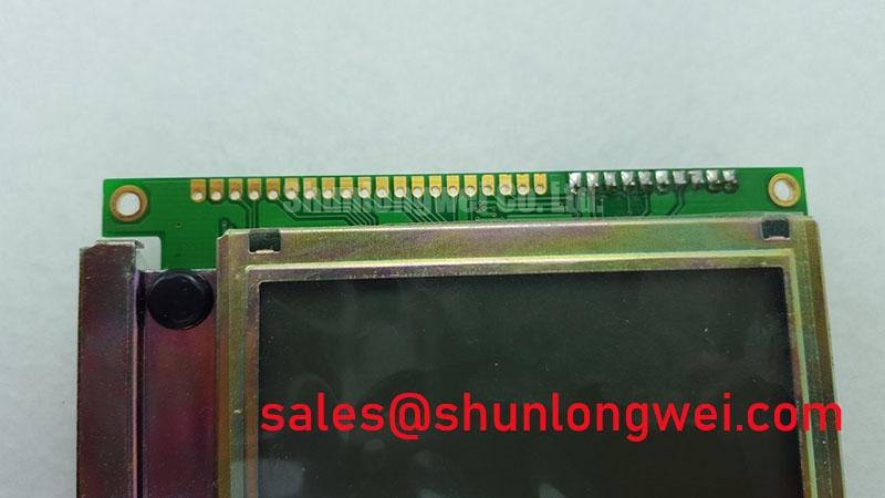
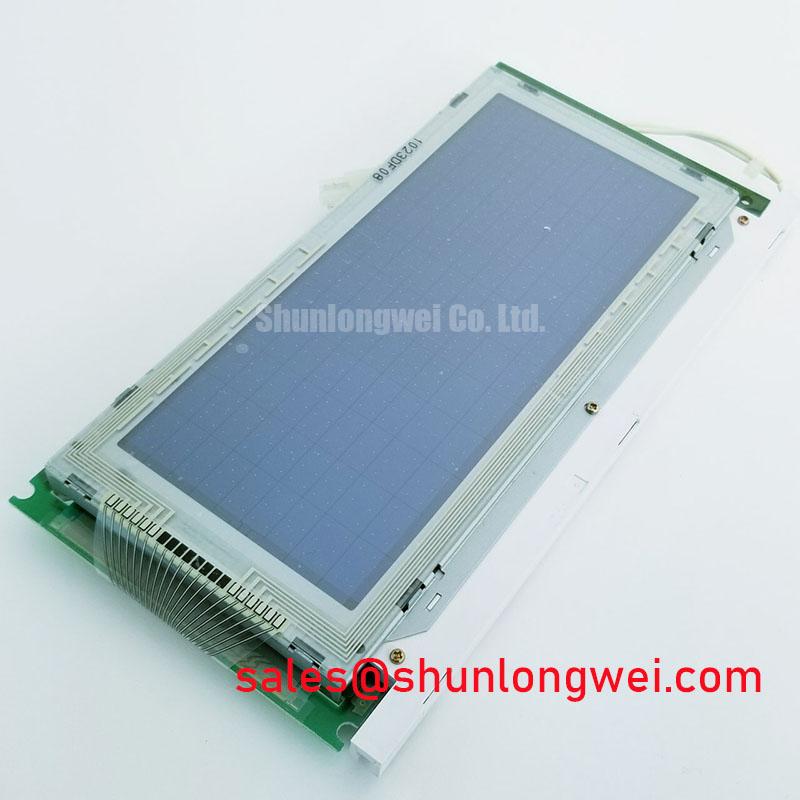
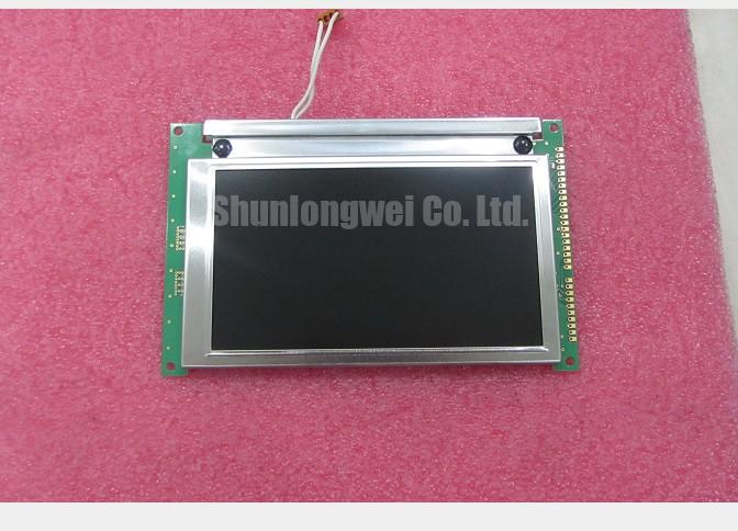
LMG7410PLFC Display Identification and Initial Inspection
Inspect the disconnected display cable for damaged contacts and uneven insertion before powering the LMG7410PLFC, then use a known-good test pattern to separate missing pixel data from uneven illumination. This Hitachi / KOE 5.1-inch STN monochrome LCD has a 240 × 128-dot resolution, CCFL backlighting, an 8-bit parallel interface, and a 5.0 V typical supply. Keep logic, LCD contrast bias, and backlight drive separate in the test record: a visible image depends on all three, but each requires different measurements.
For incoming inspection, record the full part designation, connector orientation, mounting condition, and results from uniform clear, uniform dark, alternating-line, and checkerboard patterns. These observations establish a useful baseline before assessing installation compatibility or investigating an intermittent display.
8-Bit Parallel Interface and Signal Timing Checks
Trace the host signal assignments before interpreting control waveforms. The specified interface for the LMG7410PLFC is 8-bit parallel; confirm the connector pinout and signal functions from the module documentation. Distinguish a controller-side command interface from a panel-side scanning interface before attaching probes or adapting an existing cable.
Design Consideration: Capture data and associated control signals at the display connector, where cable loading and contact resistance affect the received waveform. Compare clock relationships, data stability, and control transitions with the module and controller timing requirements. An image shifted consistently across the screen suggests a different investigation from isolated lines that appear when the harness moves; neither observation identifies a single failed component.
Check power-up and shutdown behavior alongside the signal capture. Logic activity, contrast bias, and display enable should follow the applicable module and controller sequence. LCD operation requires appropriate alternating drive across the liquid crystal; external signal names alone cannot establish whether the drive remains balanced. Avoid treating an improvised sequence as a validated means of preventing image retention or electrical damage.
During thermal checks, distinguish slower pixel transitions from corrupted data. Liquid-crystal response generally slows as temperature falls, while connector faults can produce discontinuous rows or columns. Record ambient conditions and allow the image to settle before comparing patterns, without assigning an unsupported operating-temperature range to this module.
Connector and Interconnect Integrity
Inspect the accessible cable termination and mounting frame without opening the display stack or increasing bezel pressure to suppress a missing line. Zebra-strip and heat-seal connections require different handling, and neither internal construction is established by the supplied product specifications. A pressure-sensitive symptom is a diagnostic observation, not permission to compress the assembly.
💡 Bench Tip: With power removed and ESD precautions in place, seat the cable squarely and engage its retention mechanism evenly before reconnecting power.
Design Consideration: Check for harness strain, distorted brackets, trapped cables, and uneven support around the mounting points. Photograph contact condition before cleaning. Use only connector-compatible cleaning materials and procedures; solvent migration toward the optical stack or bonded connections can introduce a second fault. Mechanical clamping force must follow the assembly specification rather than a generic pressure target.
For replacement assessment, compare the LMG7410PLFC LCD display with a separately documented candidate such as LM24010Z. The comparison below identifies the evidence needed for interchangeability; it does not establish a direct replacement.
| Compatibility item | LMG7410PLFC specification | LM24010Z assessment requirement |
|---|---|---|
| Display size | 5.1 inches | Consult datasheet and mechanical drawing |
| Resolution | 240 × 128 dots | Confirm raster and addressing compatibility |
| Display mode | STN monochrome | Confirm optical mode and viewing orientation |
| Interface | 8-bit parallel | Confirm connector pinout and timing |
| Supply | 5.0 V typical | Confirm logic and contrast supply requirements |
| Backlight | CCFL | Confirm lamp connection and inverter compatibility |
A factory automation machine-tool HMI operator terminal is a potential compatibility assessment context, subject to its controller, aperture, harness, and backlight inverter matching the display requirements. Matching resolution alone does not establish electrical or mechanical interchangeability.
Contrast Bias and Thermal Contrast Drift Checks
Measure the contrast-control path separately from the 5.0 V typical logic supply when the raster is present but text becomes faint. Record the contrast setting, supply behavior, and temperature together so that an adjustment does not conceal a changing rail or unstable connection.
Design Consideration: V_ee and V_0 describe different functions in many LCD circuits: one can identify a bias supply, while the other identifies an adjustable contrast reference. Determine their actual roles from the circuit before measuring or injecting voltage. Use a suitable probe arrangement to distinguish real ripple from pickup, and compare behavior with a known-good assembly under equivalent image and backlight conditions.
Temperature compensation should track the display’s contrast characteristic rather than apply an arbitrary negative-voltage range. Where the host includes a thermistor or programmable bias circuit, inspect its sensing location and response during gradual temperature changes. Judge contrast after stabilization and check that improving dark-state visibility does not excessively darken the background.
The CCFL backlight requires its appropriate inverter; the typical logic supply is not a lamp-drive specification. Compare lamp startup, sustained illumination, and inverter behavior with the matched system documentation. Other display products, including LM64C350, belong in a separate display-chain comparison, not in the circuit as an assumed backlight-driver accessory. No LED-driver efficiency, protection threshold, or service-life figure follows from this module’s CCFL specification.
Polarizer Condition and Optical Degradation Inspection
Compare uniform clear and dark screens under controlled ambient lighting before attributing yellowing, mottling, or reduced readability to polarizer deterioration. Repeat the observation at a fixed viewing position and backlight condition. Inspect the terminal’s cover window separately because surface contamination, scratches, or reflections can obscure an otherwise stable image.
Design Consideration: Iodine bleaching, adhesive deterioration, and vinegar syndrome describe material-specific degradation mechanisms, not confirmed construction details of the LMG7410PLFC. Neither STN operation nor CCFL illumination establishes a reflective or transflective polarizer, a particular adhesive chemistry, or an AG/AR surface treatment. Document visible discoloration, edge lifting, or bubbling without assigning an unsupported material diagnosis.
Assess backlight uniformity independently from pixel defects. Broad brightness gradients or color shifts warrant comparison across the illuminated area, while repeatable dot defects should be mapped against the test pattern. Use consistent exposure for photographs and compare equivalent screen locations. The distinction between static and dynamic contrast measurement helps prevent misleading comparisons caused by changing illumination.
For fit assessment, use the physical drawing rather than infer the viewing aperture from the dot matrix; display aspect ratio and screen form factors explain why raster proportions and enclosure geometry are separate considerations. The Ultimate Guide to Industrial TFT LCD Technology offers broader display-selection context, but TFT-specific assumptions should not be transferred to this STN module. Finish the inspection record with pixel maps, illumination photographs, connector observations, and the exact test conditions.